Основной каталог Kyocera 2016-2017 - страница 511
Навигация
 Каталог Kyocera фрезы MFH для высокоскоростной обработки
 Каталог Kyocera фрезы MEC высокопроизводительные концевые и торцевые фрезы
 Каталог микроинструмента Kyocera 2015-2016
 Каталог Kyocera высокоэффективные сверла со сменными пластинами DRV
 Каталог Kyocera пластины TQ для нарезания резьбы c прессованным стружколомом
 Каталог Kyocera высокопроизводительные модульные сверла DRA
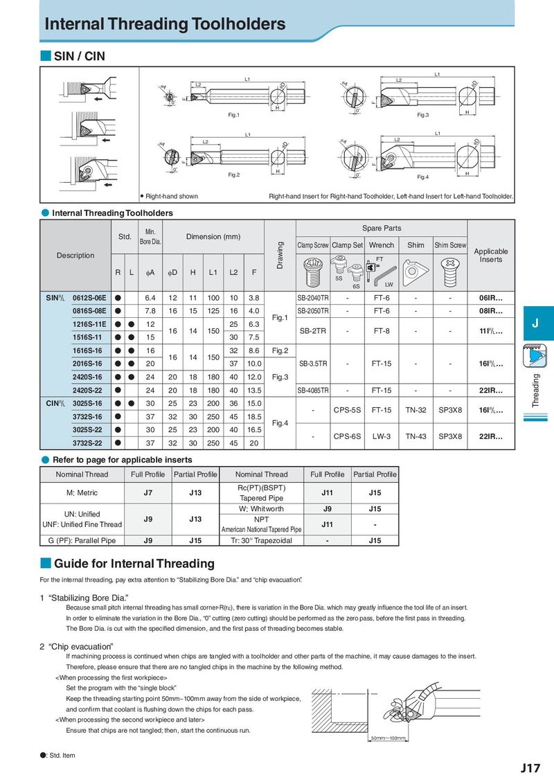
Internal Threading Toolholders
■ SIN / CIN
L1
L1 φA L2
φA L2 φD φD
F
0° F
H 0°
Fig.1 Fig.3 H
L1 L1
φA L2 φA L2 φD
φD
F F
0° H H
Fig.2 0° Fig.4
● Right-hand shown Right-hand Insert for Right-hand Toolholder, Left-hand Insert for Left-hand Toolholder.
● Internal Threading Toolholders
Min. Spare Parts
Std. Bore Dia. Dimension (mm)
Drawing Clamp Screw Clamp Set Wrench Shim Shim Screw Applicable
Description FT Inserts
R L φA φD H L1 L2 F 5S
6S LW
SIN& 0612S-06E N 6.4 12 11 100 10 3.8 SB-2040TR - FT-6 - - 06IR…
0816S-08E N 7.8 16 15 125 16 4.0 Fig.1 SB-2050TR - FT-6 - - 08IR…
1216S-11E N N 12 16 14 150 25 6.3 SB-2TR - FT-8 - - 11I&… J
1516S-11 N N 15 30 7.5
1616S-16 N N 16 16 14 150 32 8.6 Fig.2
2016S-16 N N 20 37 10.0 SB-3.5TR - FT-15 - - 16I&…
2420S-16 N N 24 20 18 180 40 12.0 Fig.3 Threading
2420S-22 N 24 20 18 180 40 13.5 SB-4085TR - FT-15 - - 22IR…
CIN& 3025S-16 N N 30 25 23 200 36 15.0 - CPS-5S FT-15 TN-32 SP3X8 16I&…
3732S-16 N 37 32 30 250 45 18.5 Fig.4
3025S-22 N 30 25 23 200 40 16.5 - CPS-6S LW-3 TN-43 SP3X8 22IR…
3732S-22 N 37 32 30 250 45 20
● Refer to page for applicable inserts
Nominal Thread Full Profile Partial Profile Nominal Thread Full Profile Partial Profile
M: Metric J7 J13 Rc(PT)(BSPT) J11 J15
Tapered Pipe
UN: Unified W: Whitworth J9 J15
UNF: Unified Fine Thread J9 J13 NPT J11 -
American National Tapered Pipe
G (PF): Parallel Pipe J9 J15 Tr: 30° Trapezoidal - J15
■ Guide for Internal Threading
For the internal threading, pay extra attention to “Stabilizing Bore Dia.” and “chip evacuation”.
1 “Stabilizing Bore Dia.”
Because small pitch internal threading has small corner-R(rε), there is variation in the Bore Dia. which may greatly influence the tool life of an insert.
In order to eliminate the variation in the Bore Dia., “0” cutting (zero cutting) should be performed as the zero pass, before the first pass in threading.
The Bore Dia. is cut with the specified dimension, and the first pass of threading becomes stable.
2 “Chip evacuation”
If machining process is continued when chips are tangled with a toolholder and other parts of the machine, it may cause damages to the insert.
Therefore, please ensure that there are no tangled chips in the machine by the following method.