Основной каталог Kyocera 2016-2017 - страница 479
Навигация
 Каталог Kyocera фрезы MFH для высокоскоростной обработки
 Каталог Kyocera фрезы MEC высокопроизводительные концевые и торцевые фрезы
 Каталог микроинструмента Kyocera 2015-2016
 Каталог Kyocera высокоэффективные сверла со сменными пластинами DRV
 Каталог Kyocera пластины TQ для нарезания резьбы c прессованным стружколомом
 Каталог Kyocera высокопроизводительные модульные сверла DRA
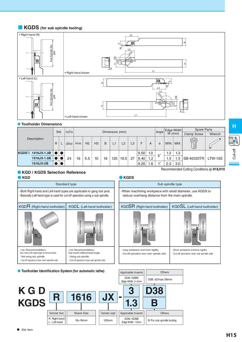
KGDS (for sub spindle tooling) • Right-hand (R) L3 F B Sub Spindle Dia. W L2 φ50 φDmax H2 H3 θ h H A • Right-hand shown L1 • Left-hand (L) F B L3 W Dia. L2 Spindle φ50 φDmax H2 Sub θ H3 H h A • Left-hand shown L1 Toolholder Dimensions H Std. Cut-off Dia. Dimension (mm) Angle Edge Width Spare Parts W (mm) Clamp Screw Wrench Description R L φDmax H=h H2 H3 B L1 L2 L3 F A θ MIN. MAX. KGDS& 1616JX-1.3B ● ● 9.50 1.0 5° 1.3 1.3 Cut-off 1616JX-1.5B ● ● 24 16 5.5 10 16 120 19.5 27 9.40 1.2 1.5 1.5 SB-40120TR LTW-15S 1616JX-2B ● ● 9.20 1.6 1° 2.0 3.0 KGD / KGDS Selection Reference Recommended Cutting Conditions H18,H19 ● KGD ● KGDS Standard type Sub spindle type · Both Right-hand and Left-hand types are applicable to gang tool post. · When machining workpiece with small diameter, use KGDS to · Basically Left-hand type is used for cut-off operation using a sub spindle. reduce overhang distance from the main spindle. KGDR (Right-hand toolholder) KGDL (Left-hand toolholder) KGDSR (Right-hand toolholder) KGDSL (Left-hand toolholder) Main Spindle Main Spindle Sub Spindle Main Spindle Sub Spindle Main Spindle Sub Spindle <1st. Recommendation> <1st. Recommendation> · Long workpiece and more rigidity · Short workpiece and less rigidity Use insert with lead angle to remove boss. Use insert without lead angle. · Cut-off operation near main spindle side · Cut-off operation near sub spindle side · Not using sub spindle · Using sub spindle · Cut-off operation near main spindle side · Cut-off operation near sub spindle side Toolholder Identification System (for automatic lathe) Applicable Inserts Others GDM / GDMS D38: φDmax 38mm Edge Width: 3~4mm KGD R 1616 JX - 3 D38 KGDS 1.3 B Toolholder Hand Shank Size Toolholder Length Applicable Inserts Others R: Right-hand 16×16mm 120mm GDM / GDMS B: For sub spindle tooling L : Left-hand Edge Width: 1.3mm N : Std. Item H15