Основной каталог Kyocera 2016-2017 - страница 475
Навигация
 Каталог Kyocera фрезы MFH для высокоскоростной обработки
 Каталог Kyocera фрезы MEC высокопроизводительные концевые и торцевые фрезы
 Каталог микроинструмента Kyocera 2015-2016
 Каталог Kyocera высокоэффективные сверла со сменными пластинами DRV
 Каталог Kyocera пластины TQ для нарезания резьбы c прессованным стружколомом
 Каталог Kyocera высокопроизводительные модульные сверла DRA
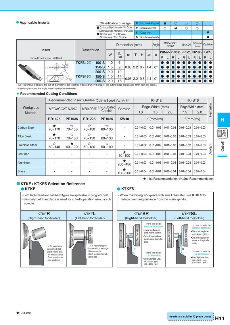
Applicable Inserts Classification of usage P Carbon steel / Alloy steel
:Continuous-Light Interruption / 1st Choice M Stainless Steel
:Continuous-Light Interruption / 2nd Choice K Cast Iron
●:Continuous / 1st Choice
○:Continuous / 2nd Choice N Non-ferrous Metals
Dimension (mm) Angle MEGACOAT MEGACOAT PVD Coated Carbide
NANO Carbide
Insert Description φD PR1425 PR1535 PR1225 PR1025 KW10
W max rε T H φd θ R L R L R L R L R L
Handed insert shows Left-Hand
φd θ ±0.03 W TKFS12& 100-S 1.0 6 ● ● ● ● ● ● ● ● ● ●
rε 150-S 1.5 9 0.05 2.2 8.7 4.4 0° ● ● ● ● ● ● ● ● ● ●
T
rε 200-S 2.0 12 ● ● ● ● ● ● ● ● ● ●
H φDmax TKFS16& 150-S 1.5 14 0.05 2.2 9.5 4.4 0° ● ● ● ● ● ● ● ● ● ●
200-S 2.0 16 ● ● ● ● ● ● ● ● ● ●
· As Fig.2 (H10) of shows, the cut-off diameter of the insert is indicated when the top of the cutting edge progresses 1mm from the center.
· Lead angle shows the angle when installed in toolholder.
Recommended Cutting Conditions
Recommended Insert Grades (Cutting Speed Vc: m/min) TKFS12 TKFS16
Workpiece MEGACOAT NANO MEGACOAT PVD Coated Carbide Edge Width (mm) Edge Width (mm) Remarks
Material Carbide 1.0 1.5 2.0 1.5 2.0
PR1425 PR1535 PR1225 PR1025 KW10 f (mm/rev) f (mm/rev) H
Carbon Steel ★ ☆ ☆ ☆ - 0.01~0.03 0.01~0.03 0.01~0.03 0.01~0.03 0.01~0.03
70~170 70~150 70~150 60~130
Alloy Steel ★ ☆ ☆ ☆ - 0.01~0.03 0.01~0.03 0.01~0.03 0.01~0.03 0.01~0.03
70~170 70~150 70~150 60~130
Stainless Steel ☆ ★ ☆ ☆ - 0.01~0.02 0.01~0.02 0.01~0.03 0.01~0.02 0.01~0.03 Coolant Cut-off
60~140 60~120 60~120 50~100
Cast Iron - - - - ★ 0.01~0.03 0.01~0.03 0.01~0.03 0.01~0.03 0.01~0.03
50~100
Aluminum - - - - ★ 0.01~0.03 0.01~0.03 0.01~0.03 0.01~0.03 0.01~0.03
200~450
Brass - - - - ★ 0.01~0.04 0.01~0.04 0.01~0.04 0.01~0.04 0.01~0.04
100~200
★ : 1st Recommendation ☆: 2nd Recommendation
KTKF / KTKFS Selection Reference
● KTKF ● KTKFS
· Both Right-hand and Left-hand types are applicable to gang tool post. · When machining workpiece with small diameter, use KTKFS to
· Basically Left-hand type is used for cut-off operation using a sub reduce overhang distance from the main spindle.
spindle.
KTKFR KTKFL KTKFSR KTKFSL
(Right-hand toolholder) (Left-hand toolholder) (Right-hand toolholder) (Left-hand toolholder)