Основной каталог Kyocera 2016-2017 - страница 453
Навигация
 Каталог Kyocera фрезы MFH для высокоскоростной обработки
 Каталог Kyocera фрезы MEC высокопроизводительные концевые и торцевые фрезы
 Каталог микроинструмента Kyocera 2015-2016
 Каталог Kyocera высокоэффективные сверла со сменными пластинами DRV
 Каталог Kyocera пластины TQ для нарезания резьбы c прессованным стружколомом
 Каталог Kyocera высокопроизводительные модульные сверла DRA
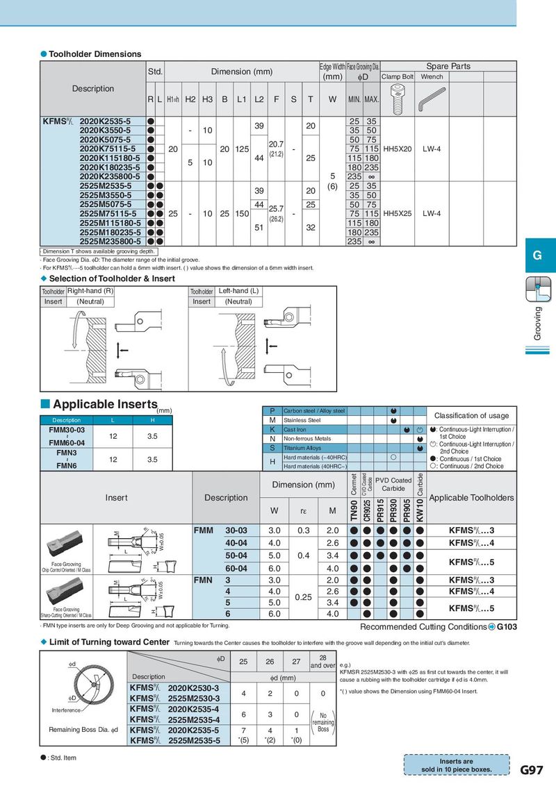
Toolholder Dimensions Std. Dimension (mm) Edge Width Face Grooving Dia. Spare Parts (mm) φD Clamp Bolt Wrench Description RL H1=h H2 H3 B L1 L2 F S T W MIN. MAX. KFMS& 2020K2535-5 ● 39 20 25 35 2020K3550-5 ● - 10 35 50 2020K5075-5 ● 20.7 50 75 2020K75115-5 ● 20 20 125 (21.2) - 75 115 HH5X20 LW-4 2020K115180-5 ● 5 10 44 25 115 180 2020K180235-5 ● 180 235 2020K235800-5 ● 5 235 ∞ 2525M2535-5 ●● 39 20 (6) 25 35 2525M3550-5 ●● 35 50 2525M5075-5 ●● 44 25.7 25 50 75 2525M75115-5 ●● 25 - 10 25 150 (26.2) - 75 115 HH5X25 LW-4 2525M115180-5 ●● 51 32 115 180 2525M180235-5 ●● 180 235 2525M235800-5 ●● 235 ∞ · Dimension T shows available grooving depth. G · Face Grooving Dia. φD: The diameter range of the initial groove. · For KFMS&···-5 toolholder can hold a 6mm width insert. ( ) value shows the dimension of a 6mm width insert. Selection of Toolholder & Insert Toolholder Right-hand (R) Toolholder Left-hand (L) Insert (Neutral) Insert (Neutral) Grooving Applicable Inserts (mm) P Carbon steel / Alloy steel Description L H M Stainless Steel Classification of usage FMM30-03 K Cast Iron : Continuous-Light Interruption / ~ 12 3.5 N Non-ferrous Metals 1st Choice FMM60-04 S Titanium Alloys : Continuous-Light Interruption / FMN3 2nd Choice ~ 12 3.5 H Hard materials (~40HRC) : Continuous / 1st Choice FMN6 Hard materials (40HRC~) : Continuous / 2nd Choice Dimension (mm) Cermet CVD Coated Carbide PVD Coated Carbide Carbide Insert Description TN90 CR9025 PR915 PR930 PR905 KW10 Applicable Toolholders FMM20-02を示す W rε M M rH 2゜ FMM 30-03 3.0 0.3 2.0 ● ● ● ● ● ● KFMS&…3 2゜ W±0.05 40-04 4.0 2.6 ● ● ● ● ● ● KFMS&…4 L rH 50-04 5.0 0.4 3.4 ● ● ● ● ● ● Face Grooving H 60-04 6.0 4.0 ● ● ● ● ● KFMS&…5 Chip Control Oriented / M Class M rH 2° W±0.05 FMN 3 3.0 2.0 ● ● ● ● KFMS&…3 4 4.0 0.25 2.6 ● ● ● ● KFMS&…4 L rH 2° 5 5.0 3.4 ● ● ● ● Face Grooving H 6 6.0 4.0 ● ● ● KFMS&…5 Sharp-Cutting Oriented / M Class · FMN type inserts are only for Deep Grooving and not applicable for Turning. Recommended Cutting Conditions G103 Limit of Turning toward Center Turning towards the Center causes the toolholder to interfere with the groove wall depending on the initial cut's diameter. φD 25 26 27 28 Id and over e.g.) Description φd (mm) KFMSR 2525M2530-3 with φ25 as first cut towards the center, it will cause a rubbing with the toolholder cartridge if φd is 4.0mm. KFMS& 2020K2530-3 4 2 0 0 *( ) value shows the Dimension using FMM60-04 Insert. ID KFMS& 2525M2530-3 Interference KFMS& 2020K2535-4 6 3 0 No KFMS& 2525M2535-4 remaining Remaining Boss Dia. φd KFMS& 2020K2535-5 7 4 1 Boss KFMS& 2525M2535-5 *(5) *(2) *(0) : Std. Item Inserts are sold in 10 piece boxes. G97