Основной каталог Kyocera 2016-2017 - страница 446
Навигация
 Каталог Kyocera фрезы MFH для высокоскоростной обработки
 Каталог Kyocera фрезы MEC высокопроизводительные концевые и торцевые фрезы
 Каталог микроинструмента Kyocera 2015-2016
 Каталог Kyocera высокоэффективные сверла со сменными пластинами DRV
 Каталог Kyocera пластины TQ для нарезания резьбы c прессованным стружколомом
 Каталог Kyocera высокопроизводительные модульные сверла DRA
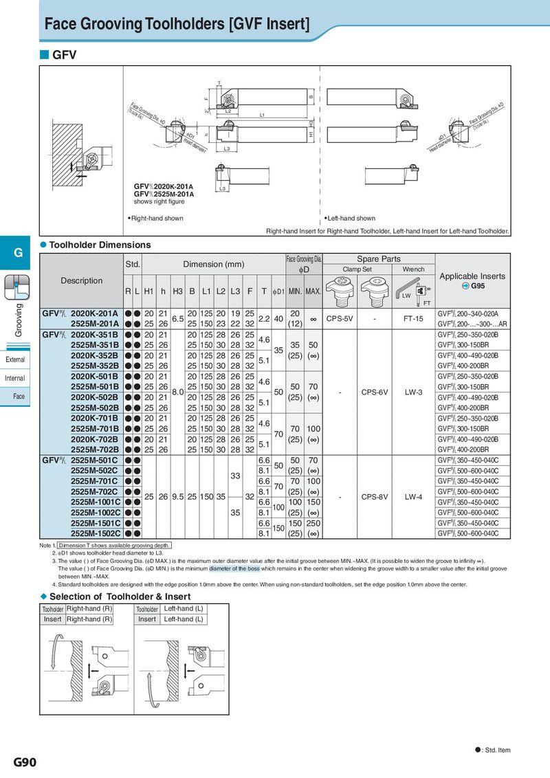
Face Grooving Toolholders [GVF Insert] GFV T F B (ToFoautceer dGia.)rooving Dia. ID 2° L2 Fa(cTeo oGutreor doiav.i)ng Dia. ID L1 H3 HeIaDd 1dia1meter h H1 Head dIiDam1eter L3 GFV&2020K-201A L3 GFV&2525M-201A shows right figure Right-hand shown Left-hand shown Right-hand Insert for Right-hand Toolholder, Left-hand Insert for Left-hand Toolholder. G Toolholder Dimensions Std. Dimension (mm) Face Grooving Dia. Spare Parts φD Clamp Set Wrench Description Applicable Inserts RL H1 h H3 B L1 L2 L3 F T φD1 MIN. MAX. G95 LW Grooving FT GFV& 2020K-201A ●● 20 21 6.5 20 125 20 19 25 2.2 40 20 ∞ CPS-5V - FT-15 GVF&200~340-020A 2525M-201A ●● 25 26 25 150 23 22 32 (12) GVF&200-…~300-…AR GFV& 2020K-351B ●● 20 21 20 125 28 26 25 4.6 GVF&250~350-020B 2525M-351B ●● 25 26 25 150 30 28 32 35 35 50 GVF&300-150BR External 2020K-352B ●● 20 21 20 125 28 26 25 5.1 (25) (∞) GVF&400~490-020B 2525M-352B ●● 25 26 25 150 30 28 32 GVF&400-200BR Internal 2020K-501B ●● 20 21 20 125 28 26 25 4.6 GVF&250~350-020B 2525M-501B ●● 25 26 8.0 25 150 30 28 32 50 50 70 - CPS-6V LW-3 GVF&300-150BR Face 2020K-502B ●● 20 21 20 125 28 26 25 5.1 (25) (∞) GVF&400~490-020B 2525M-502B ●● 25 26 25 150 30 28 32 GVF&400-200BR 2020K-701B ●● 20 21 20 125 28 26 25 4.6 GVF&250~350-020B 2525M-701B ●● 25 26 25 150 30 28 32 70 70 100 GVF&300-150BR 2020K-702B ●● 20 21 20 125 28 26 25 5.1 (25) (∞) GVF&400~490-020B 2525M-702B ●● 25 26 25 150 30 28 32 GVF&400-200BR GFV& 2525M-501C ●● 6.6 50 50 70 GVF&350~450-040C 2525M-502C ●● 33 8.1 (25) (∞) GVF&500~600-040C 2525M-701C ●● 6.6 70 70 100 GVF&350~450-040C 2525M-702C ●● 25 26 9.5 25 150 35 32 8.1 (25) (∞) - CPS-8V LW-4 GVF&500~600-040C 2525M-1001C ●● 6.6 100 100 150 GVF&350~450-040C 2525M-1002C ●● 35 8.1 (25) (∞) GVF&500~600-040C 2525M-1501C ●● 6.6 150 150 250 GVF&350~450-040C 2525M-1502C ●● 8.1 (25) (∞) GVF&500~600-040C Note 1. Dimension T shows available grooving depth. 2. φD1 shows toolholder head diameter to L3. 3. The value ( ) of Face Grooving Dia. (φD MAX.) is the maximum outer diameter value after the initial groove between MIN.~MAX. (It is possible to widen the groove to infinity ∞). The value ( ) of Face Grooving Dia. (φD MIN.) is the minimum diameter of the boss which remains in the center when widening the groove width to a smaller value after the initial groove between MIN.~MAX. 4. Standard toolholders are designed with the edge position 1.0mm above the center. When using non-standard toolholders, set the edge position 1.0mm above the center. Selection of Toolholder & Insert Toolholder Right-hand (R) Toolholder Left-hand (L) Insert Right-hand (R) Insert Left-hand (L) : Std. Item G90