Основной каталог Kyocera 2016-2017 - страница 432
Навигация
 Каталог Kyocera фрезы MFH для высокоскоростной обработки
 Каталог Kyocera фрезы MEC высокопроизводительные концевые и торцевые фрезы
 Каталог микроинструмента Kyocera 2015-2016
 Каталог Kyocera высокоэффективные сверла со сменными пластинами DRV
 Каталог Kyocera пластины TQ для нарезания резьбы c прессованным стружколомом
 Каталог Kyocera высокопроизводительные модульные сверла DRA
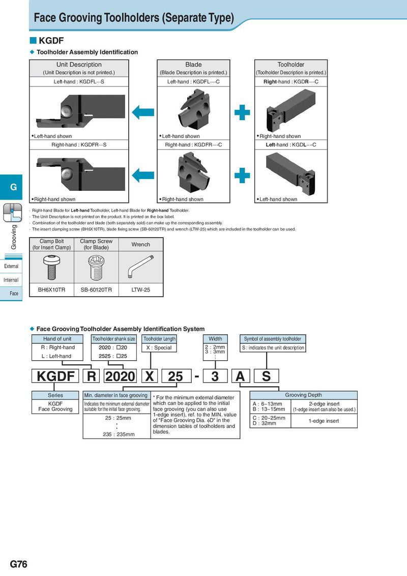
Face Grooving Toolholders (Separate Type) KGDF Toolholder Assembly Identification Unit Description Blade Toolholder (Unit Description is not printed.) (Blade Description is printed.) (Toolholder Description is printed.) Left-hand : KGDFL···S Left-hand : KGDFL···-C Right-hand : KGDR···-C Left-hand shown Left-hand shown Right-hand shown Right-hand : KGDFR···S Right-hand : KGDFR···-C Left-hand : KGDL···-C G Right-hand shown Right-hand shown Left-hand shown · Right-hand Blade for Left-hand Toolholder, Left-hand Blade for Right-hand Toolholder. · The Unit Description is not printed on the product. It is printed on the box label. Grooving · Combination of the toolholder and blade (both separately sold) can make up the corresponding assembly. · The insert clamping screw (BH6X10TR), blade fixing screw (SB-60120TR) and wrench (LTW-25) which are included in the toolholder can be used. Clamp Bolt Clamp Screw Wrench (for Insert Clamp) (for Blade) External Internal Face BH6X10TR SB-60120TR LTW-25 Face Grooving Toolholder Assembly Identification System Hand of unit Toolholder shank size Toolholder Length Width Symbol of assembly toolholder R : Right-hand X : Special 2㸯2mm S : indicates the unit description 3㸯3mm L : Left-hand … KGDF R 2020 X 25 - 3 A S Series Min. diameter in face grooving * For the minimum external diameter Grooving Depth KGDF Indicates the minimum external diameter which can be applied to the initial A㸯6~13mm 2-edge insert Face Grooving suitable for the initial face grooving. face grooving (you can also use B㸯13~15mm (1-edge insert can also be used.) 25㸯25mm 1-edge insert), ref. to the MIN. value C㸯20~25mm ࣬ of "Face Grooving Dia. ID" in the D㸯32mm 1-edge insert ࣬ dimension tables of toolholders and 235㸯235mm blades. G76