Основной каталог Kyocera 2016-2017 - страница 405
Навигация
 Каталог Kyocera фрезы MFH для высокоскоростной обработки
 Каталог Kyocera фрезы MEC высокопроизводительные концевые и торцевые фрезы
 Каталог микроинструмента Kyocera 2015-2016
 Каталог Kyocera высокоэффективные сверла со сменными пластинами DRV
 Каталог Kyocera пластины TQ для нарезания резьбы c прессованным стружколомом
 Каталог Kyocera высокопроизводительные модульные сверла DRA
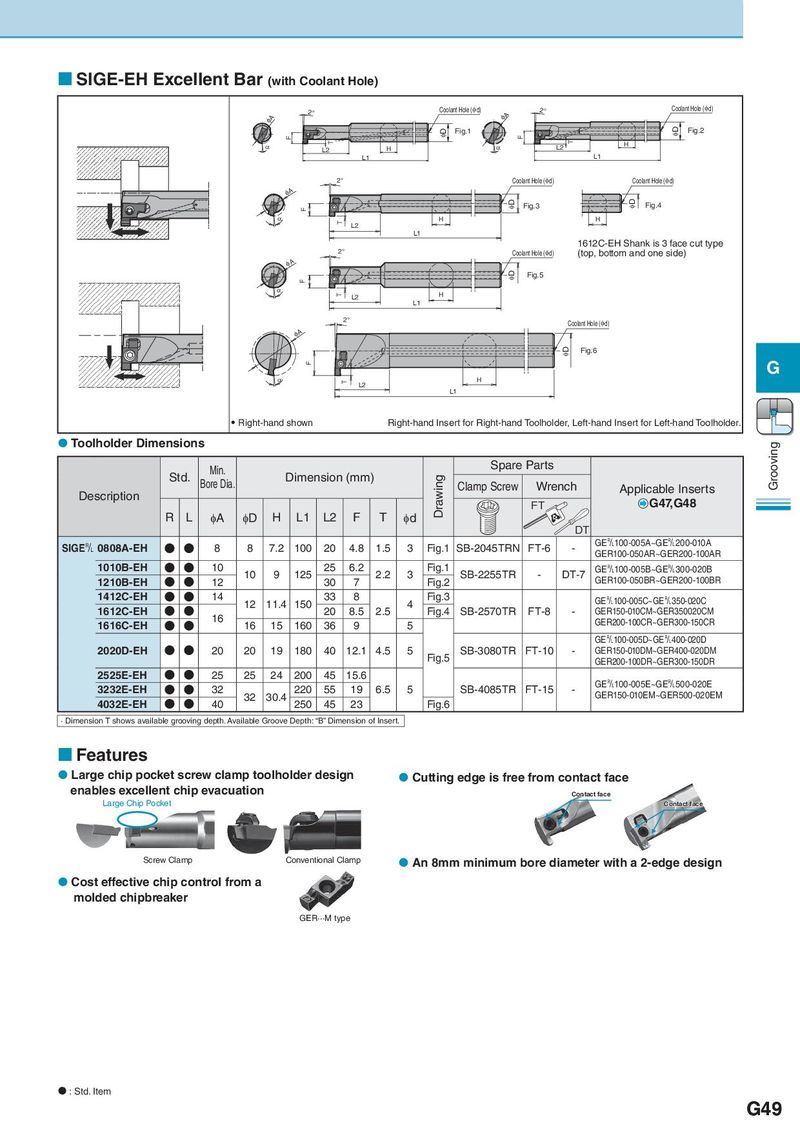
SIGE-EH Excellent Bar (with Coolant Hole) 2° Coolant Hole (φd) 2° Coolant Hole (φd) φA φA φD Fig.1 φD Fig.2 F F T T H α L2 H α L2 L1 L1 2° Coolant Hole (φd) Coolant Hole (φd) φA F φD Fig.3 φD Fig.4 α T H H L2 L1 1612C-EH Shank is 3 face cut type 2° Coolant Hole (φd) (top, bottom and one side) φA φD Fig.5 F α T H L2 L1 2° Coolant Hole (φd) φA φD Fig.6 F G α T L2 H L1 Right-hand shown Right-hand Insert for Right-hand Toolholder, Left-hand Insert for Left-hand Toolholder. Toolholder Dimensions Grooving Min. Spare Parts Std. Bore Dia. Dimension (mm) Drawing Clamp Screw Wrench Description Applicable Inserts FT G47,G48 R L φA φD H L1 L2 F T φd DT SIGE& 0808A-EH N N 8 8 7.2 100 20 4.8 1.5 3 Fig.1 SB-2045TRN FT-6 - GE&100-005A~GE&200-010A GER100-050AR~GER200-100AR 1010B-EH N N 10 10 9 125 25 6.2 2.2 3 Fig.1 SB-2255TR - DT-7 GE&100-005B~GE&300-020B 1210B-EH N N 12 30 7 Fig.2 GER100-050BR~GER200-100BR 1412C-EH N N 14 12 11.4 150 33 8 4 Fig.3 GE&100-005C~GE&350-020C 1612C-EH N N 16 20 8.5 2.5 Fig.4 SB-2570TR FT-8 - GER150-010CM~GER350020CM 1616C-EH N N 16 15 160 36 9 5 GER200-100CR~GER300-150CR GE&100-005D~GE&400-020D 2020D-EH N N 20 20 19 180 40 12.1 4.5 5 Fig.5 SB-3080TR FT-10 - GER150-010DM~GER400-020DM GER200-100DR~GER300-150DR 2525E-EH N N 25 25 24 200 45 15.6 GE&100-005E~GE&500-020E 3232E-EH N N 32 32 30.4 220 55 19 6.5 5 SB-4085TR FT-15 - GER150-010EM~GER500-020EM 4032E-EH N N 40 250 45 23 Fig.6 · Dimension T shows available grooving depth. Available Groove Depth: “B” Dimension of Insert. Features Large chip pocket screw clamp toolholder design Cutting edge is free from contact face enables excellent chip evacuation Contact face Large Chip Pocket Contact face Screw Clamp Conventional Clamp An 8mm minimum bore diameter with a 2-edge design Cost effective chip control from a molded chipbreaker GER···M type : Std. Item G49