Основной каталог Kyocera 2016-2017 - страница 401
Навигация
 Каталог Kyocera фрезы MFH для высокоскоростной обработки
 Каталог Kyocera фрезы MEC высокопроизводительные концевые и торцевые фрезы
 Каталог микроинструмента Kyocera 2015-2016
 Каталог Kyocera высокоэффективные сверла со сменными пластинами DRV
 Каталог Kyocera пластины TQ для нарезания резьбы c прессованным стружколомом
 Каталог Kyocera высокопроизводительные модульные сверла DRA
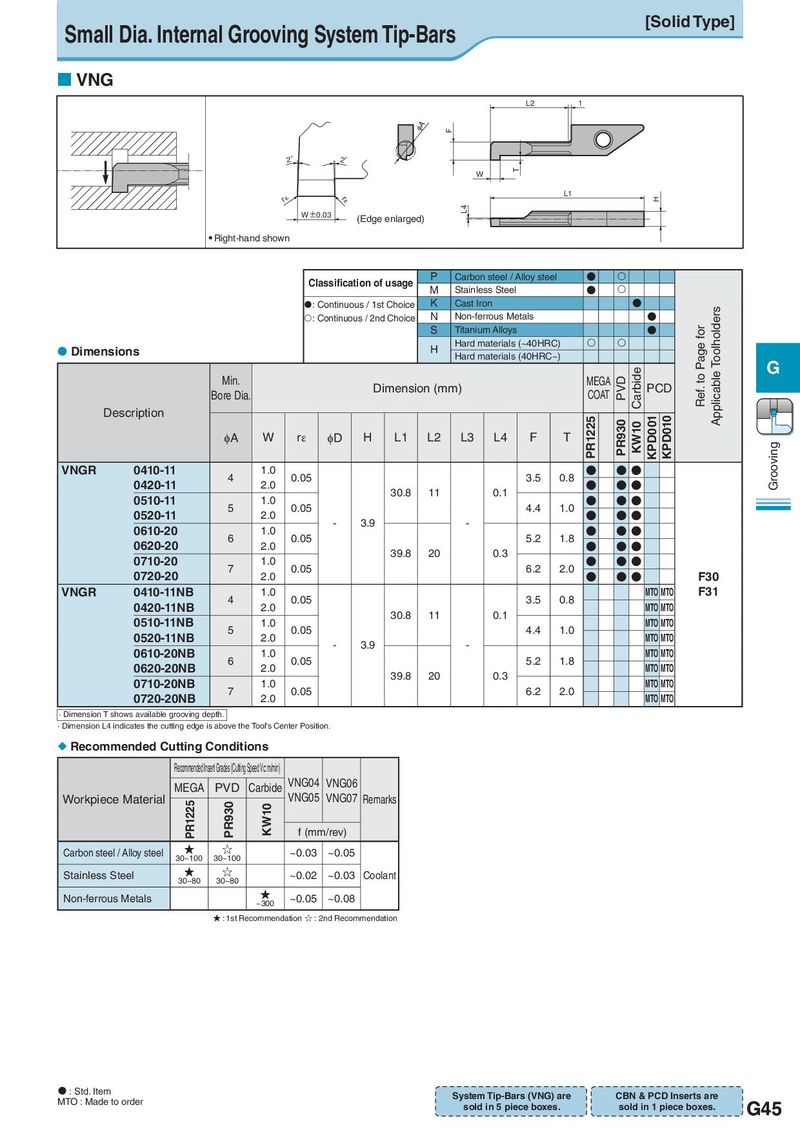
Small Dia. Internal Grooving System Tip-Bars [Solid Type] VNG L2 1 qA F 2° 2° W T r¡ L1 H r¡ W±0.03 L4 (Edge enlarged) Right-hand shown Classification of usage P Carbon steel / Alloy steel ● M Stainless Steel ● :Continuous / 1st Choice K Cast Iron ● Applicable Toolholders :Continuous / 2nd Choice N Non-ferrous Metals ● S Titanium Alloys ● Ref. to Page for Dimensions H Hard materials (~40HRC) Hard materials (40HRC~) G Min. Dimension (mm) MEGA PVD Carbide PCD Bore Dia. COAT Description PR1225 KPD001 KPD010 φA W rε φD H L1 L2 L3 L4 F T PR930 KW10 Grooving VNGR 0410-11 4 1.0 0.05 3.5 0.8 ● ● ● 0420-11 2.0 30.8 11 0.1 ● ● ● 0510-11 5 1.0 0.05 4.4 1.0 ● ● ● 0520-11 2.0 - 3.9 - ● ● ● 0610-20 6 1.0 0.05 5.2 1.8 ● ● ● 0620-20 2.0 39.8 20 0.3 ● ● ● 0710-20 7 1.0 0.05 6.2 2.0 ● ● ● 0720-20 2.0 ● ● ● F30 VNGR 0410-11NB 4 1.0 0.05 3.5 0.8 MTO MTO F31 0420-11NB 2.0 30.8 11 0.1 MTO MTO 0510-11NB 5 1.0 0.05 4.4 1.0 MTO MTO 0520-11NB 2.0 - 3.9 - MTO MTO 0610-20NB 6 1.0 0.05 5.2 1.8 MTO MTO 0620-20NB 2.0 39.8 20 0.3 MTO MTO 0710-20NB 7 1.0 0.05 6.2 2.0 MTO MTO 0720-20NB 2.0 MTO MTO · Dimension T shows available grooving depth. · Dimension L4 indicates the cutting edge is above the Tool's Center Position. Recommended Cutting Conditions Recommended Insert Grades (Cut ing Speed Vc: m/min) MEGA PVD Carbide VNG04 VNG06 Workpiece Material PR1225 PR930 KW10 VNG05 VNG07 Remarks f (mm/rev) Carbon steel / Alloy steel ★ ☆ ~0.03 ~0.05 30~100 30~100 Stainless Steel ★ ☆ ~0.02 ~0.03 Coolant 30~80 30~80 Non-ferrous Metals ★ ~0.05 ~0.08 ~300 ★ : 1st Recommendation ☆ : 2nd Recommendation : Std. Item System Tip-Bars (VNG) are CBN & PCD Inserts are MTO : Made to order sold in 5 piece boxes. sold in 1 piece boxes. G45