Основной каталог Kyocera 2016-2017 - страница 393
Навигация
 Каталог Kyocera фрезы MFH для высокоскоростной обработки
 Каталог Kyocera фрезы MEC высокопроизводительные концевые и торцевые фрезы
 Каталог микроинструмента Kyocera 2015-2016
 Каталог Kyocera высокоэффективные сверла со сменными пластинами DRV
 Каталог Kyocera пластины TQ для нарезания резьбы c прессованным стружколомом
 Каталог Kyocera высокопроизводительные модульные сверла DRA
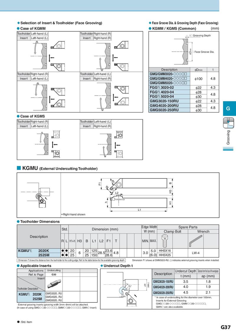
Selection of Insert & Toolholder (Face Grooving) Face Groove Dia. & Grooving Depth (Face Grooving) Case of KGMM KGMM / KGMS (Common) (mm) Toolholder Left-hand (L) Toolholder Right-hand (R) t:Grooving Depth Insert Left-hand (L) Insert Right-hand (R) IDmin :Face Groove Dia. Description φDmin t Toolholder Right-hand (R) Toolholder Left-hand (L) GMG/GMM3020- Insert Left-hand (L) Insert Right-hand (R) GMG/GMM4020- φ100 4.8 GMG/GMM5020- FGG&3020-02 φ22 4.3 FGG&4020-04 φ28 4.8 FGG&5020-04 φ30 GMG3020-150RU φ22 4.3 GMG4020-200RU φ28 4.8 G GMG5020-250RU φ30 Case of KGMS Toolholder Right-hand (R) Toolholder Left-hand (L) Insert Left-hand (L) Insert Right-hand (R) Grooving KGMU (External Undercutting Toolholder) F1 45° B W T L2 H3 h H1 L1 • Right-hand shown Toolholder Dimensions Std. Dimension (mm) Edge Width Spare Parts W (mm) Clamp Bolt Wrench Description RL H1=h H3 B L1 L2 F1 T MIN. MAX. KGMU& 2020K 20 6 20 125 28.5 23.6 4.8 3.0 5.0 HH5X16 LW-4 2525M 25 25 150 28.6 (6.0) HH5X25 · Dimension T shows the distance from the toolholder to the cutting edge. Ref. to the table below for the available grooving depth. Dimension F1 shows at GMM5020-RU. ( ) indicates external grooving inserts when installed. Applicable Inserts Undercut Depth t Applications Undercutting Undercut Depth Distancefromthefaceoftheworkpiece Ref. to Page G30 Description t (mm) ap (mm) Insert (MIN.) GMG3020-150RU 3.5 1.8 t I20 GMG4020-200RU 4.0 1.9 Toolholder Description GMG3020..RU ap GMG5020-250RU 4.5 2.1 KGMU& 2020K GMG4020..RU ap 2525M * In case of undercutting for the diameter over 100mm, GMG5020..RU Inserts for External Grooving · External grooving inserts (grooving width 3mm~6mm) will be attached. GMG20-, GMM20-, (In case of using GMG20-, GMM20-, GMN insert) GMN are also available. : Std. Item G37