Основной каталог Kyocera 2016-2017 - страница 371
Навигация
 Каталог Kyocera фрезы MFH для высокоскоростной обработки
 Каталог Kyocera фрезы MEC высокопроизводительные концевые и торцевые фрезы
 Каталог микроинструмента Kyocera 2015-2016
 Каталог Kyocera высокоэффективные сверла со сменными пластинами DRV
 Каталог Kyocera пластины TQ для нарезания резьбы c прессованным стружколомом
 Каталог Kyocera высокопроизводительные модульные сверла DRA
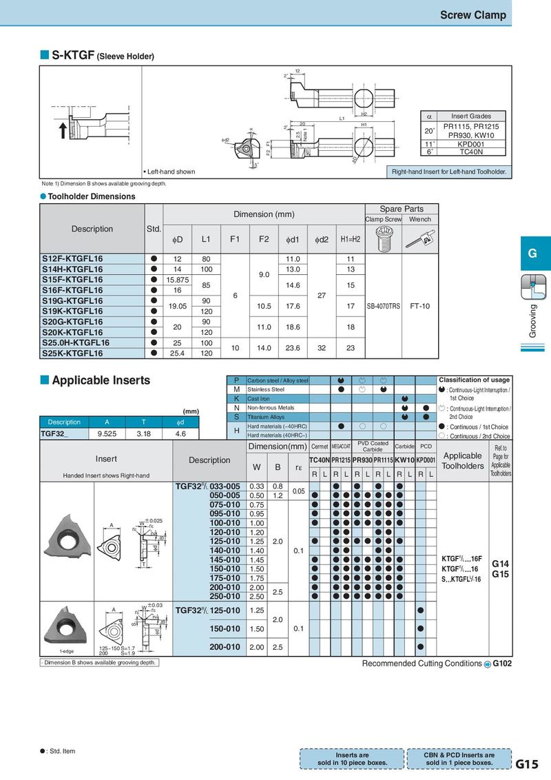
Screw Clamp S-KTGF (Sleeve Holder) 12 2゜ H2 α Insert Grades L1 2゜ 20 H1 PR1115, PR1215 D Note 1 20˚ 2.5 PR930, KW10 Id2 F1 11˚ KPD001 F2 Id1 6˚ TC40N ID 5゜ • Left-hand shown Right-hand Insert for Left-hand Toolholder. Note 1) Dimension B shows available grooving depth. Toolholder Dimensions Dimension (mm) Spare Parts Clamp Screw Wrench Description Std. φD L1 F1 F2 φd1 φd2 H1=H2 S12F-KTGFL16 12 80 11.0 11 G S14H-KTGFL16 14 100 9.0 13.0 13 S15F-KTGFL16 15.875 85 14.6 15 S16F-KTGFL16 16 6 27 S19G-KTGFL16 19.05 90 10.5 17.6 17 SB-4070TRS FT-10 Grooving S19K-KTGFL16 120 S20G-KTGFL16 20 90 11.0 18.6 18 S20K-KTGFL16 120 S25.0H-KTGFL16 25 100 10 14.0 23.6 32 23 S25K-KTGFL16 25.4 120 Applicable Inserts P Carbon steel / Alloy steel Q P P Classification of usage M Stainless Steel N P Q Q : Continuous-Light Interruption / K Cast Iron Q 1st Choice (mm) N Non-ferrous Metals Q N P : Continuous-Light Interruption / Description A T φd S Titanium Alloys Q N 2nd Choice H Hard materials (~40HRC) N O O N : Continuous / 1st Choice TGF32_ 9.525 3.18 4.6 Hard materials (40HRC~) O : Continuous / 2nd Choice Dimension(mm) Cermet MEGACOAT PVD Coated Carbide PCD Ref. to Carbide Insert Description TC40N PR1215 PR930 PR1115 KW10 KPD001 Applicable Page for W B rε Toolholders Applicable Handed Insert shows Right-hand R L R L R L R L R L R L Toolholders TGF32& 033-005 0.33 0.8 0.05 050-005 0.50 1.2 075-010 0.75 095-010 0.95 A W±r0H.025 100-010 1.00 2゜ rH 120-010 1.20 B 125-010 1.25 2.0 Id 140-010 1.40 0.1 T 145-010 1.45 KTGF&…16F G14 150-010 1.50 KTGF&…16 G15 175-010 1.75 S…KTGFL 16 200-010 2.00 2.5 250-010 2.50 A rH W±r0H.03 TGF32& 125-010 1.25 2゜ 2.0 S B Id 150-010 1.50 0.1 1-edge 125~150 S=1.7 T 200-010 2.00 2.5 200 S=1.9 · Dimension B shows available grooving depth. Recommended Cutting Conditions G102 : Std. Item Inserts are CBN & PCD Inserts are sold in 10 piece boxes. sold in 1 piece boxes. G15