Основной каталог Kyocera 2016-2017 - страница 34
Навигация
 Каталог Kyocera фрезы MFH для высокоскоростной обработки
 Каталог Kyocera фрезы MEC высокопроизводительные концевые и торцевые фрезы
 Каталог микроинструмента Kyocera 2015-2016
 Каталог Kyocera высокоэффективные сверла со сменными пластинами DRV
 Каталог Kyocera пластины TQ для нарезания резьбы c прессованным стружколомом
 Каталог Kyocera высокопроизводительные модульные сверла DRA
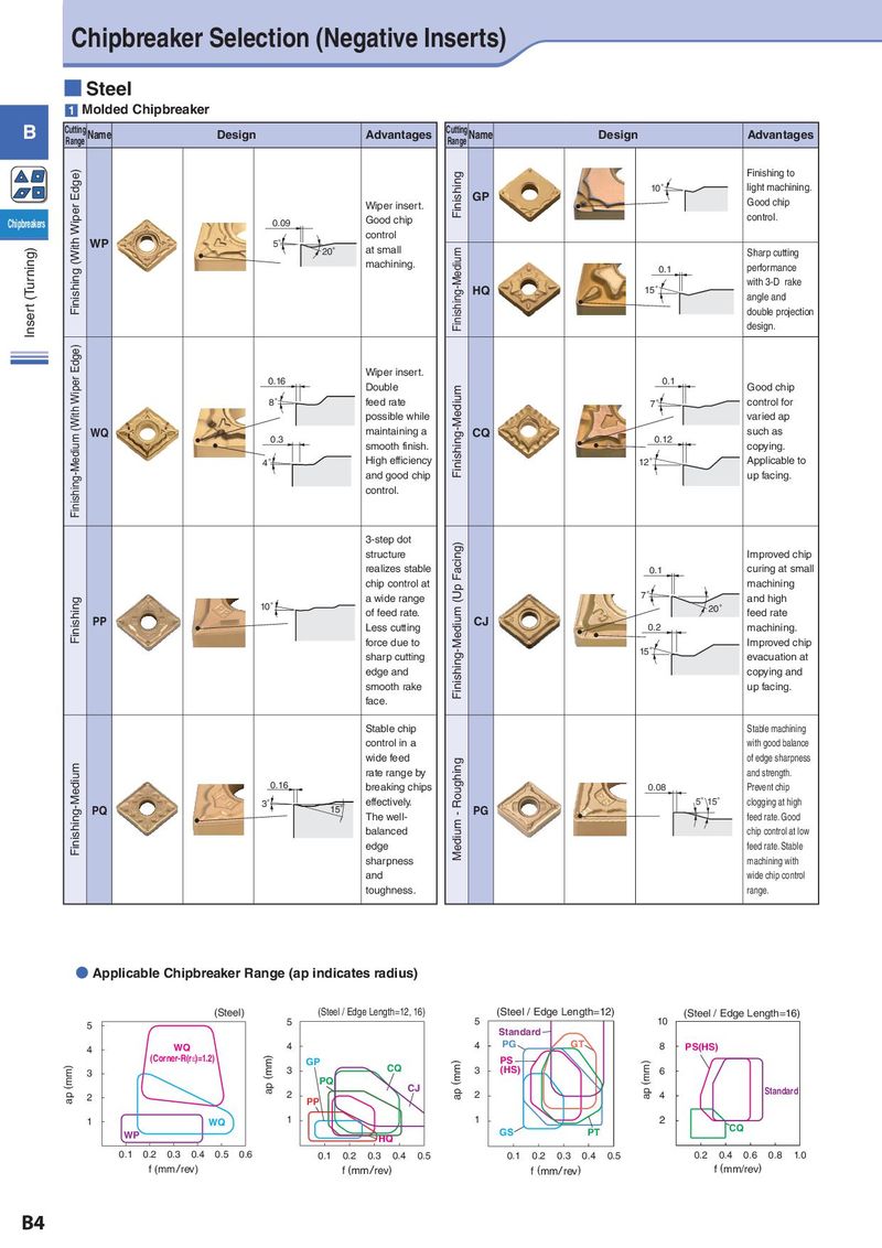
Chipbreaker Selection (Negative Inserts) ■ Steel 1 Molded Chipbreaker B Cutting Name Design Advantages Cutting Name Design Advantages Range Range Finishing (With Wiper Edge) Finishing Finishing to GP 10° light machining. Wiper insert. Good chip Chipbreakers 0.09 Good chip control. WP 5° control Insert (Turning) 20° at small Finishing-Medium Sharp cutting machining. 0.1 performance HQ 15° with 3-D rake angle and double projection design. Finishing-Medium (With Wiper Edge) 0.16 Wiper insert. Double Finishing-Medium 0.1 Good chip 8° feed rate 7° control for possible while varied ap WQ 0.3 maintaining a CQ 0.12 such as smooth finish. copying. 4° High efficiency 12° Applicable to and good chip up facing. control. 3-step dot Facing) structure Improved chip realizes stable 0.1 curing at small chip control at Finishing-Medium (Up machining Finishing a wide range 7° and high 10° of feed rate. 20° feed rate PP Less cutting CJ 0.2 machining. force due to Improved chip sharp cutting 15° evacuation at edge and copying and smooth rake up facing. face. Stable chip Stable machining control in a with good balance Finishing-Medium wide feed Medium - Roughing of edge sharpness rate range by and strength. 0.16 breaking chips 0.08 Prevent chip PQ 3° 15° effectively. PG 5°15° clogging at high The well- feed rate. Good balanced chip control at low edge feed rate. Stable sharpness machining with and wide chip control toughness. range. ● Applicable Chipbreaker Range (ap indicates radius) (Steel) (Steel / Edge Length=12, 16) (Steel / Edge Length=12) (Steel / Edge Length=16) 5 5 5 10 Standard 4 WQ 4 4 PG GT 8 PS(HS) (Corner-R(rH)=1.2) ap (mm) GP ap (mm) PS ap (mm) ap (mm) 3 3 CQ 3 (HS) 6 PQ CJ 2 2 2 4 Standard PP 1 WQ 1 1 2 CQ WP HQ GS PT 0.1 0.2 0.3 0.4 0.5 0.6 0.1 0.2 0.3 0.4 0.5 0.1 0.2 0.3 0.4 0.5 0.2 0.4 0.6 0.8 1.0 f (mm/rev) f (mm/rev) f (mm/rev) f (mm/rev) B4