Основной каталог Kyocera 2016-2017 - страница 32
Навигация
 Каталог Kyocera фрезы MFH для высокоскоростной обработки
 Каталог Kyocera фрезы MEC высокопроизводительные концевые и торцевые фрезы
 Каталог микроинструмента Kyocera 2015-2016
 Каталог Kyocera высокоэффективные сверла со сменными пластинами DRV
 Каталог Kyocera пластины TQ для нарезания резьбы c прессованным стружколомом
 Каталог Kyocera высокопроизводительные модульные сверла DRA
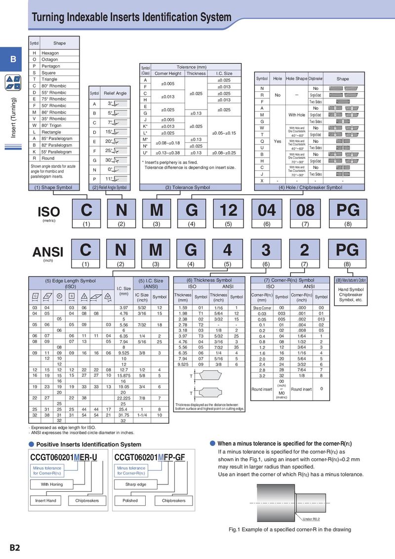
Turning Indexable Inserts Identification System Symbol Shape H Hexagon B O Octagon P Pentagon Symbol Tolerance (mm) S Square (Class) Corner Height Thickness I.C. Size T Triangle A ±0.025 Symbol Hole Hole Shape Chipbreaker Shape C 80° Rhombic F ±0.005 ±0.013 N No D 55° Rhombic Symbol Relief Angle C ±0.025 ±0.025 R No − Single Sided Insert (Turning) E 75° Rhombic H ±0.013 ±0.013 A 3° F Two Sides F 50° Rhombic E A No M 86° Rhombic B 5° G ±0.025 ±0.13 ±0.025 M With Hole Single Sided V 35° Rhombic 7° J ±0.005 G Two Sides W 80° Trigon C K* ±0.013 ±0.025 W With Hole and No L Rectangle D 15° L* ±0.025 ±0.05~±0.15 One Countersink T 40°~60° Single Sided A 85° Parallelogram E 20° M* ±0.13 Q Yes With Hole and No B 82° Parallelogram N* ±0.08~±0.18 ±0.025 Two Countersink F 25° U 40°~60° Two Sides K 55° Parallelogram U* ±0.13~±0.38 ±0.13 ±0.08~±0.25 B With Hole and No R Round G 30° One Countersink * Insert's periphery is as fired. H 70°~90° Single Sided Shown angle stands for acute N 0° Tolerance difference is depending on insert size. C With Hole and No angle for rhombic and Two Countersink parallelogram inserts. J 70°~90° Two Sides P 11° X - - - - (1) Shape Symbol (2) Relief Angle Symbol (3) Tolerance Symbol (4) Hole / Chipbreaker Symbol ISO C N M G 12 04 08 PG (metric) (1) (2) (3) (4) (5) (6) (7) (8) ANSI C N M G 4 3 2 PG (inch) (1) (2) (3) (4) (5) (6) (7) (8) (5) Edge Length Symbol (5) I.C. Size (6) Thickness Symbol (7) Corner-R(rH) Symbol (8) Manufacturer’s Option (ISO) I.C. Size (ANSI) ISO ANSI ISO ANSI Hand Symbol C D R S T V W (mm) IC Size Symbol Thickness Symbol Thickness Symbol Corner-R(rH) Symbol Corner-R(rH) Symbol Chipbreaker (inch) (mm) (inch) (mm) (inch) Symbol, etc. 03 04 03 06 3.97 5/32 12 1.59 01 1/16 1 Sharp Corner 00 .000 00 04 05 04 08 08 4.76 3/16 15 1.98 T1 5/64 12 0.03 003 .001 01 05 5 2.38 02 3/32 15 0.05 005 .002 013 05 06 05 09 03 5.56 7/32 18 2.78 T2 - - 0.1 01 .004 02 06 6 3.18 03 1/8 2 0.2 02 .008 05 06 07 06 11 11 04 6.35 1/4 2 3.97 T3 5/32 25 0.4 04 1/64 1 08 09 07 13 05 7.94 5/16 25 4.76 04 3/16 3 0.8 08 1/32 2 08 8 5.56 05 7/32 35 1.2 12 3/64 3 09 11 09 09 16 16 06 9.525 3/8 3 6.35 06 1/4 4 1.6 16 1/16 4 12 10 10 7.94 07 5/16 5 2.0 20 5/64 5 12 12 9.525 09 3/8 6 2.4 24 3/32 6 12 15 12 12 22 22 08 12.7 1/2 4 2.8 28 7/64 7 16 19 15 15 27 27 10 15.875 5/8 5 T 3.2 32 1/8 8 16 16 00 19 23 19 19 33 33 13 19.05 3/4 6 (inch) 0 Round insert or Round insert 20 20 T M0 22 27 22 38 22.225 7/8 7 (metric) 25 25 Thickness displayed as the distance between 25 31 25 25 44 44 17 25.4 1 8 bottom surface and highest point on cutting edge. 32 38 31 31 54 54 21 31.75 1-1/4 10 32 32 · Expressed as edge length for ISO. · ANSI expresses the inscribed circle diameter in inches. ● Positive Inserts Identification System ● When a minus tolerance is specified for the corner-R(re) CCGT060201MER-U CCGT060201MFP-GF If a minus tolerance is specified for the corner-R(re) as shown in the Fig.1, using an insert with corner-R(re)=0.2 mm Minus tolerance Minus tolerance may result in larger radius than specified. for Corner-R(re) for Corner-R(re) Use an insert the corner of which R(re) has a minus tolerance. With Honing Sharp edge Insert Hand Chipbreakers Polished Chipbreakers Under R0.2 Fig.1 Example of a specified corner-R in the drawing B2