Основной каталог Kyocera 2016-2017 - страница 285
Навигация
 Каталог Kyocera фрезы MFH для высокоскоростной обработки
 Каталог Kyocera фрезы MEC высокопроизводительные концевые и торцевые фрезы
 Каталог микроинструмента Kyocera 2015-2016
 Каталог Kyocera высокоэффективные сверла со сменными пластинами DRV
 Каталог Kyocera пластины TQ для нарезания резьбы c прессованным стружколомом
 Каталог Kyocera высокопроизводительные модульные сверла DRA
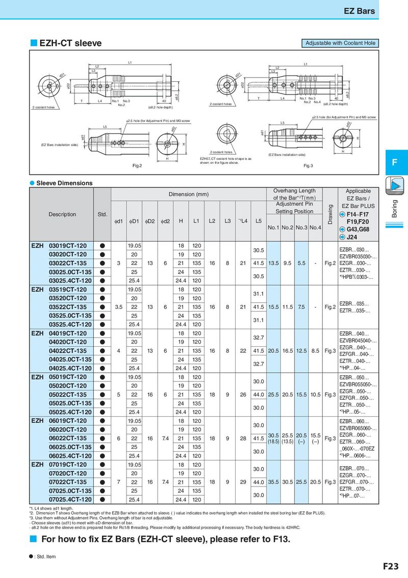
EZEZBBaarsr EZH-CT sleeve Adjustable with Coolant Hole L1 L1 L2 L2 L3 L3 φD1 φD1 φD2 φD2 φ8.2 T L4 No.1 No.3 40 φ8.2 T L4 No.1 No.3 40 No.2 No.4 No.2 2 coolant holes (φ8.2 hole depth) 2 coolant holes (φ8.2 hole depth) φ2.5 hole (for Adjustment Pin) and M3 screw φ2.5 hole (for Adjustment Pin) and M3 screw L5 φd2 L5 φd2 φd1 φd1 H (EZ Bars installation side) H 2 coolant holes H (EZ Bars installation side) H EZH07..CT coolant hole shape is as F Fig.2 shown on the figure above. Fig.3 Sleeve Dimensions Dimension (mm) Overhang Length Applicable of the Bar*2T(mm) EZ Bars / Boring Adjustment Pin Drawing EZ Bar PLUS Description Std. Setting Position F14~F17 φd1 φD1 φD2 φd2 H L1 L2 L3 *1L4 L5 F19,F20 No.1 No.2 No.3 No.4 G43,G68 J24 EZH 03019CT-120 ● 19.05 18 120 30.5 EZBR…030… 03020CT-120 ● 20 19 120 EZVBR035030-… 03022CT-135 ● 3 22 13 6 21 135 16 8 21 41.5 13.5 9.5 5.5 - Fig.2 EZGR…030-… 03025.0CT-135 ● 25 24 135 EZTR…030-… 03025.4CT-120 ● 25.4 24.4 120 30.5 *3HPB&0303-… EZH 03519CT-120 ● 19.05 18 120 31.1 03520CT-120 ● 20 19 120 03522CT-135 ● 3.5 22 13 6 21 135 16 8 21 41.5 15.5 11.5 7.5 - Fig.2 EZBR…035… EZTR…035-… 03525.0CT-135 ● 25 24 135 31.1 03525.4CT-120 ● 25.4 24.4 120 EZH 04019CT-120 ● 19.05 18 120 32.7 EZBR…040… 04020CT-120 ● 20 19 120 EZVBR045040-… 04022CT-135 ● 4 22 13 6 21 135 16 8 22 41.5 20.5 16.5 12.5 8.5 Fig.3 EZGR…040-… EZFGR…040-… 04025.0CT-135 ● 25 24 135 32.7 EZTR…040-… 04025.4CT-120 ● 25.4 24.4 120 *3HP…04-… EZH 05019CT-120 ● 19.05 18 120 30.0 EZBR…050… 05020CT-120 ● 20 19 120 EZVBR055050-… 05022CT-135 ● 5 22 16 6 21 135 18 9 26 44.0 25.5 20.5 15.5 10.5 Fig.3 EZGR…050-… EZFGR…050-… 05025.0CT-135 ● 25 24 135 30.0 EZTR…050-… 05025.4CT-120 ● 25.4 24.4 120 *3HP…05-… EZH 06019CT-120 ● 19.05 18 120 30.0 EZBR…060… 06020CT-120 ● 20 19 120 EZVBR065060-… 06022CT-135 ● 6 22 16 7.4 21 135 18 9 28 41.5 30.5 25.5 20.5 15.5 Fig.3 EZGR…060-… (18.5) (13.5) (−) (−) EZTR…060-… 06025.0CT-135 ● 25 24 135 30.0 _060X-…-070EZ 06025.4CT-120 ● 25.4 24.4 120 *3HP…0606-… EZH 07019CT-120 ● 19.05 18 120 30.0 EZBR…070… 07020CT-120 ● 20 19 120 EZGR…070-… 07022CT-135 ● 7 22 16 7.4 21 135 18 9 29 44.0 35.5 30.5 25.5 20.5 Fig.3 EZFGR…070-… 07025.0CT-135 ● 25 24 135 EZTR…070-… 07025.4CT-120 ● 25.4 24.4 120 30.0 *3HP…07-… *1. L4 shows φd1 length. *2. Dimension T shows Overhang length of the EZB Bar when attached to sleeve. ( ) value indicates the overhang length when installed the steel boring bar (EZ Bar PLUS). *3. Use them without Adjustment Pins. Overhang length of bar is not adjustable. · Choose sleeves (φd1) to meet with φD dimension of bar. · φ8.2 hole on the sleeve end is prepared hole for Rc1/8 threading. Please modify by additional processing if necessary. The body hardness is 42HRC. For how to fix EZ Bars (EZH-CT sleeve), please refer to F13. N : Std. Item F23