Основной каталог Kyocera 2016-2017 - страница 170
Навигация
 Каталог Kyocera фрезы MFH для высокоскоростной обработки
 Каталог Kyocera фрезы MEC высокопроизводительные концевые и торцевые фрезы
 Каталог микроинструмента Kyocera 2015-2016
 Каталог Kyocera высокоэффективные сверла со сменными пластинами DRV
 Каталог Kyocera пластины TQ для нарезания резьбы c прессованным стружколомом
 Каталог Kyocera высокопроизводительные модульные сверла DRA
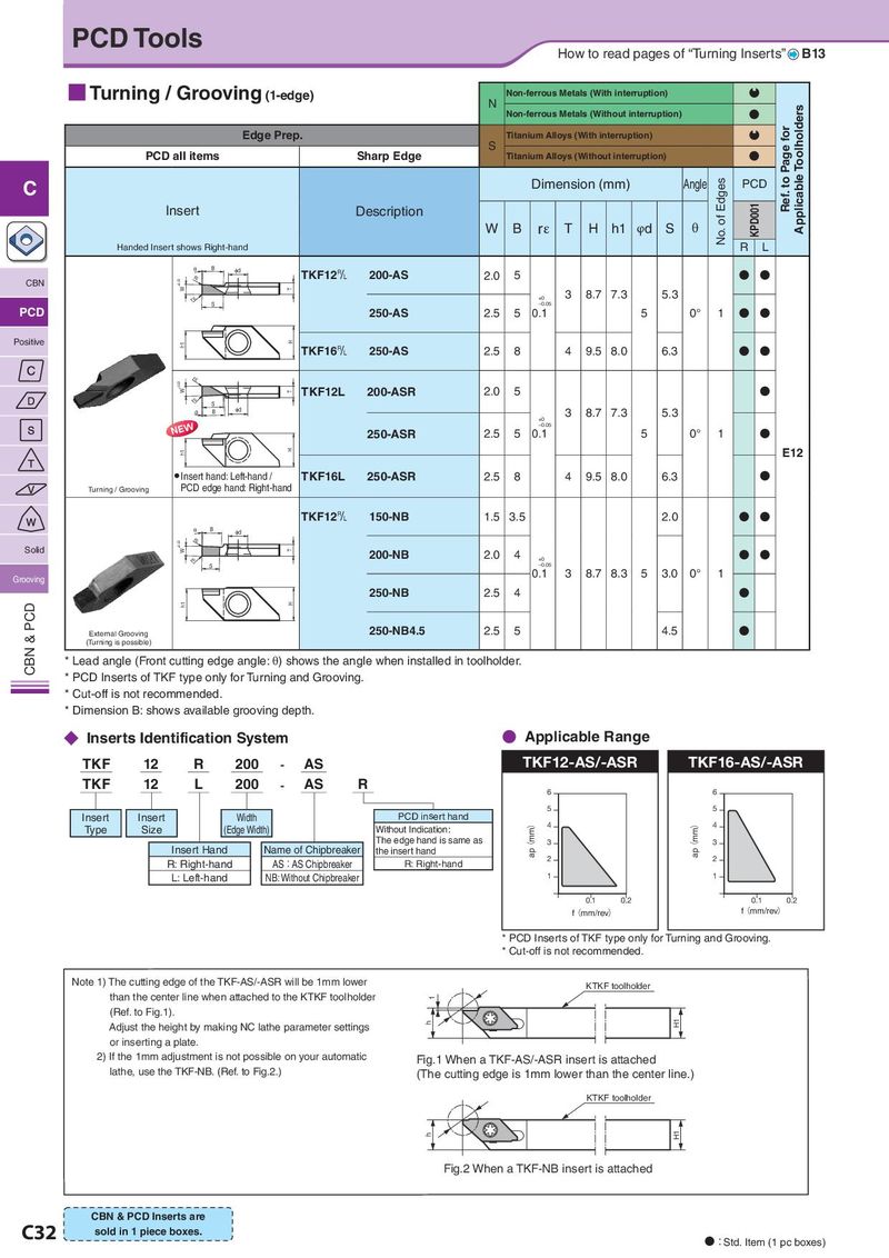
PCD Tools How to read pages of “Turning Inserts” B13 ■ Turning / Grooving (1-edge) Non-ferrous Metals (With interruption) Q N Applicable Toolholders Non-ferrous Metals (Without interruption) N Edge Prep. Titanium Alloys (With interruption) Q Ref. to Page for S PCD all items Sharp Edge Titanium Alloys (Without interruption) N C Dimension (mm) Angle No. of Edges PCD Insert Description KPD001 W B rε T H h1 φd S θ Handed Insert shows Right-hand R L T B Id TKF12& 200-AS 2.0 5 N N CBN ±0.03 rH W T 3 8.7 7.3 5.3 rH +0 S –0.05 PCD 250-AS 2.5 5 0.1 5 0° 1 N N Positive h1 H TKF16& 250-AS 2.5 8 4 9.5 8.0 6.3 N N ±0.03 rH W T TKF12L 200-ASR 2.0 5 N rH S T B Id 3 8.7 7.3 5.3 +0 1(: –0.05 250-ASR 2.5 5 0.1 5 0° 1 N h1 H E12 ● Insert hand: Left-hand / TKF16L 250-ASR 2.5 8 4 9.5 8.0 6.3 N Turning / Grooving PCD edge hand: Right-hand TKF12& 150-NB 1.5 3.5 2.0 N N T B Id ±0.03 rH Solid W T 200-NB 2.0 4 N N rH +0 S –0.05 Grooving 0.1 3 8.7 8.3 5 3.0 0° 1 250-NB 2.5 4 N PCD h1 H & External Grooving 250-NB4.5 2.5 5 4.5 N (Turning is possible) CBN * Lead angle (Front cutting edge angle: θ) shows the angle when installed in toolholder. * PCD Inserts of TKF type only for Turning and Grooving. * Cut-off is not recommended. * Dimension B: shows available grooving depth. ◆ Inserts Identification System ● Applicable Range TKF 12 R 200 - AS TKF12-AS/-ASR TKF16-AS/-ASR TKF 12 L 200 - AS R 6 6 PCD insert hand 5 5 Insert Insert Width ap(mm) 4 ap(mm) 4 Type Size (Edge Width) Without Indication: The edge hand is same as 3 3 Insert Hand Name of Chipbreaker the insert hand R: Right-hand AS:AS Chipbreaker R: Right-hand 2 2 L: Left-hand NB: Without Chipbreaker 1 1 0.1 0.2 0.1 0.2 f(mm/rev) f(mm/rev) * PCD Inserts of TKF type only for Turning and Grooving. * Cut-off is not recommended. Note 1) The cutting edge of the TKF-AS/-ASR will be 1mm lower KTKF toolholder than the center line when attached to the KTKF toolholder 1 (Ref. to Fig.1). Adjust the height by making NC lathe parameter settings h H1 or inserting a plate. 2) If the 1mm adjustment is not possible on your automatic Fig.1 When a TKF-AS/-ASR insert is attached lathe, use the TKF-NB. (Ref. to Fig.2.) (The cutting edge is 1mm lower than the center line.) KTKF toolholder h H1 Fig.2 When a TKF-NB insert is attached CBN & PCD Inserts are C32 sold in 1 piece boxes. N:Std. Item (1 pc boxes)