Основной каталог Kyocera 2016-2017 - страница 127
Навигация
 Каталог Kyocera фрезы MFH для высокоскоростной обработки
 Каталог Kyocera фрезы MEC высокопроизводительные концевые и торцевые фрезы
 Каталог микроинструмента Kyocera 2015-2016
 Каталог Kyocera высокоэффективные сверла со сменными пластинами DRV
 Каталог Kyocera пластины TQ для нарезания резьбы c прессованным стружколомом
 Каталог Kyocera высокопроизводительные модульные сверла DRA
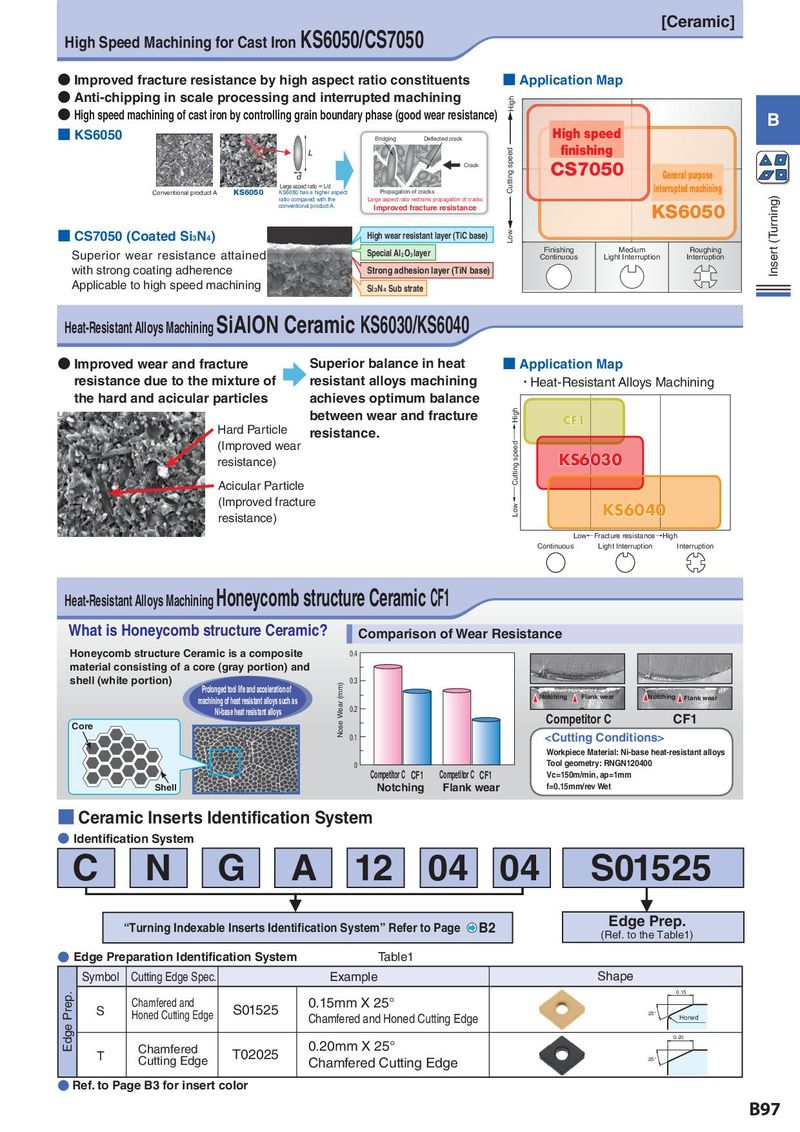
High Speed Machining for Cast Iron KS6050/CS7050 [Ceramic]
● Improved fracture resistance by high aspect ratio constituents ■ Application Map
● Anti-chipping in scale processing and interrupted machining High
● High speed machining of cast iron by controlling grain boundary phase (good wear resistance) B
■ KS6050 Bridging Deflected crack High speed
L speed finishing
Crack CS7050
d Cutting General purpose
Large aspect ratio = L/d interrupted machining
Conventional product A KS6050 KS6050 has a higher aspect Propagation of cracks
ratio compared with the Large aspect ratio restrains propagation of cracks (Turning)
conventional product A. Improved fracture resistance KS6050
■ CS7050 (Coated Si3N4) High wear resistant layer (TiC base) Low
Superior wear resistance attained Special Al2O3 layer Finishing Medium Roughing Inser t
Continuous Light Interruption Interruption
with strong coating adherence Strong adhesion layer (TiN base)
Applicable to high speed machining Si3N4 Sub strate
Heat-Resistant Alloys Machining SiAlON Ceramic KS6030/KS6040
● Improved wear and fracture Superior balance in heat ■ Application Map
resistance due to the mixture of resistant alloys machining ・Heat-Resistant Alloys Machining
the hard and acicular particles achieves optimum balance
between wear and fracture High CF1
Hard Particle resistance.
(Improved wear Cutting speed→
resistance) KS6030
Acicular Particle
(Improved fracture Low ← KS6040
resistance)
Low←Fracture resistance→High
Continuous Light Interruption Interruption
Heat-Resistant Alloys Machining Honeycomb structure Ceramic CF1
What is Honeycomb structure Ceramic? Comparison of Wear Resistance
Honeycomb structure Ceramic is a composite 0.4
material consisting of a core (gray portion) and
shell (white portion) Nose Wear (mm) 0.3
Prolonged tool life and acceleration of
machining of heat resistant alloys such as Notching Flank wear Notching Flank wear
Ni-base heat resistant alloys 0.2
Core Competitor C CF1
0.1