Основной каталог Kyocera 2016-2017 - страница 103
Навигация
 Каталог Kyocera фрезы MFH для высокоскоростной обработки
 Каталог Kyocera фрезы MEC высокопроизводительные концевые и торцевые фрезы
 Каталог микроинструмента Kyocera 2015-2016
 Каталог Kyocera высокоэффективные сверла со сменными пластинами DRV
 Каталог Kyocera пластины TQ для нарезания резьбы c прессованным стружколомом
 Каталог Kyocera высокопроизводительные модульные сверла DRA
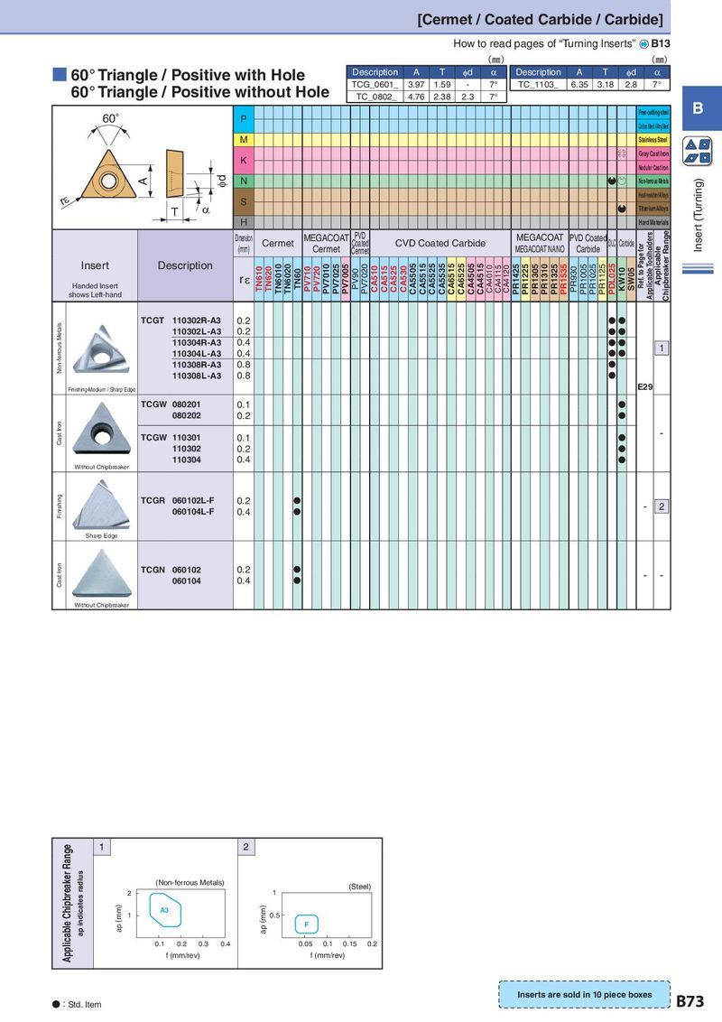
[Cermet / Coated Carbide / Carbide] How to read pages of “Turning Inserts” B13 (㎜) (㎜) ■ 60° Triangle / Positive with Hole Description A T φd α Description A T φd α 60° Triangle / Positive without Hole TCG_0601_ 3.97 1.59 - 7° TC_1103_ 6.35 3.18 2.8 7° TC_0802_ 4.76 2.38 2.3 7° 60° P Free-cutting steel B Carbon Steel / Al oy Steel M Stainless Steel K S Gray Cast Iron Nodular Cast Iron A Id N QP Non-ferrous Metals (Turning) rH S Heat-resistant Alloys T D Q Titanium Alloys H Hard Materials Inser t Dimension MEGACOAT PVD MEGACOAT PVD Coated Applicable Toolholders Chipbreaker Range Cermet Coated CVD Coated Carbide DLC Carbide (mm) Cermet Cermet MEGACOAT NANO Carbide Ref. to Page for Applicable Insert Description TN610 TN620 TN6010 TN6020 TN60 PV710 PV720 PV7010 PV7025 PV7005 PV90 PV7020 CA510 CA515 CA525 CA530 CA5505 CA5515 CA5525 CA5535 CA6515 CA6525 CA4505 CA4515 CA4010 CA4115 CA4120 PR1425 PR1225 PR1305 PR1310 PR1325 PR1535 PR930 PR1005 PR1025 PR1125 PDL025 KW10 SW05 Handed Insert rε shows Left-hand Non-ferrous Metals TCGT 110302R-A3 0.2 N N 110302L-A3 0.2 NN 110304R-A3 0.4 N N 1 110304L-A3 0.4 N N 110308R-A3 0.8 N N 110308L-A3 0.8 Finishing-Medium / Sharp Edge E29 TCGW 080201 0.1 N 080202 0.2 N Cast Iron TCGW 110301 0.1 N - 110302 0.2 N 110304 0.4 N Without Chipbreaker Finishing TCGR 060102L-F 0.2 N - 2 060104L-F 0.4 N Sharp Edge Cast Iron TCGN 060102 0.2 N - - 060104 0.4 N Without Chipbreaker Applicable Chipbreaker Range 1 2 ap indicates radius (mm) (Non-ferrous Metals) (mm) (Steel) 2 1 ap (mm) 1 A3 ap (mm) 0.5 F 0.1 0.2 0.3 0.4 0.05 0.1 0.15 0.2 f (mm/rev) f (mm/rev) Inserts are sold in 10 piece boxes B73 ●:Std. Item