Токарные пластины серии KCU10B с технологией покрытия KENGold PVD Kennametal 2023 - страница 73
Навигация
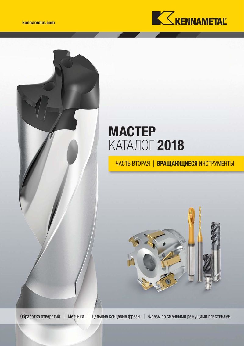 Основной каталог Kennametal вращающиеся инструменты 2018
 Новинки Kennametal - весна 2025
 Оптимальный выбор Kennametal 2025 - 2026
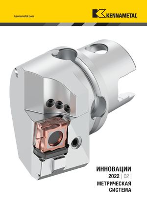 Каталог Kennametal инновации 2022.2
 Инструментальные патроны системы SAFE-LOCK Kennametal 2024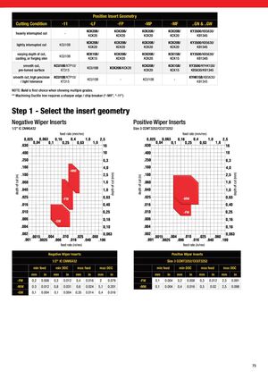
Positive Insert Geometry Cutting Condition -11 -LF -FP -MP -MF ..GN & ..GW KCK20B/ KCK20B/ KCK20B/ KCK20B/ KY3500/KB5630/ heavily interrupted cut - KCK20 KCK20 KCK20 KCK20 KB1345 KCK20B/ KCK20B/ KCK20B/ KCK20B/ KY3500/KB5630/ lightly interrupted cut KCU10B KCK20 KCK20 KCK20 KCK20 KB1345 varying depth of cut, KCK15B/ KCK20B/ KCK20B/ KCK15B/ KY3500/KB5630/ KCU10B casting, or forging skin KCK15 KCK20 KCK20 KCK15 KB1345 smooth cut, KCU10B/KTP10/ KCK20B/ KCK15B/ KY3500/KYHK15B/ KCU10B KCK20B/KCK20 pre-turned surface KT315 KCK20 KCK15 KB5630/KB1345 smooth cut, high precision KCU10B/KTP10/ KYHK15B/KB5630/ KCU10B - KCU10B - / tight tolerance KT315 KB1345 NOTE: Bold is first choice when showing multiple grades. ** Machining Ductile Iron requires a sharper edge / chip breaker (“-MR”, “-11”) Step 1 - Select the insert geometry Negative Wiper Inserts Positive Wiper Inserts 1/2” IC CNMG432 Size 3 CCMT3252/CCGT3252 feed rate (mm/rev) feed rate (mm/rev) -MW depth of cut (mm) depth of cut (mm) depth of cut (in) depth of cut (in) -FW -MW -FW -GW feed rate (in/rev) feed rate (in/rev) Negative Wiper Inserts Positive Wiper Inserts 1/2" IC CNMG432 Size 3 CCMT3252/CCGT3252 min feed min DOC max feed max DOC min feed min DOC max feed max DOC mm in mm in mm in mm in mm in mm in mm in mm in -FW 0,2 0.008 0,3 0.012 0,4 0.016 2 0.079 -FW 0,1 0.004 0,2 0.008 0,3 0.012 2,3 0.091 -MW 0.3 0.012 0,8 0.031 0,6 0.024 5,1 0.201 -MW 0,1 0.004 0,4 0.016 0,5 0.02 2,5 0.098 -GW 0,1 0.004 0,1 0.004 0,35 0.014 0,4 0.016 73