Каталог Iscar вращающийся инструмент 2017 - страница 886
Навигация
 Каталог Iscar токарные пластины ISO 2022
 Каталог Iscar инструмент для фрезерования
 Каталог Iscar решения для глубокого сверления
 Каталог Iscar полирующие фрезы
 Каталог Iscar новые продукты 2018
 Каталог Iscar концевые фрезы со сменными пластинами 2022
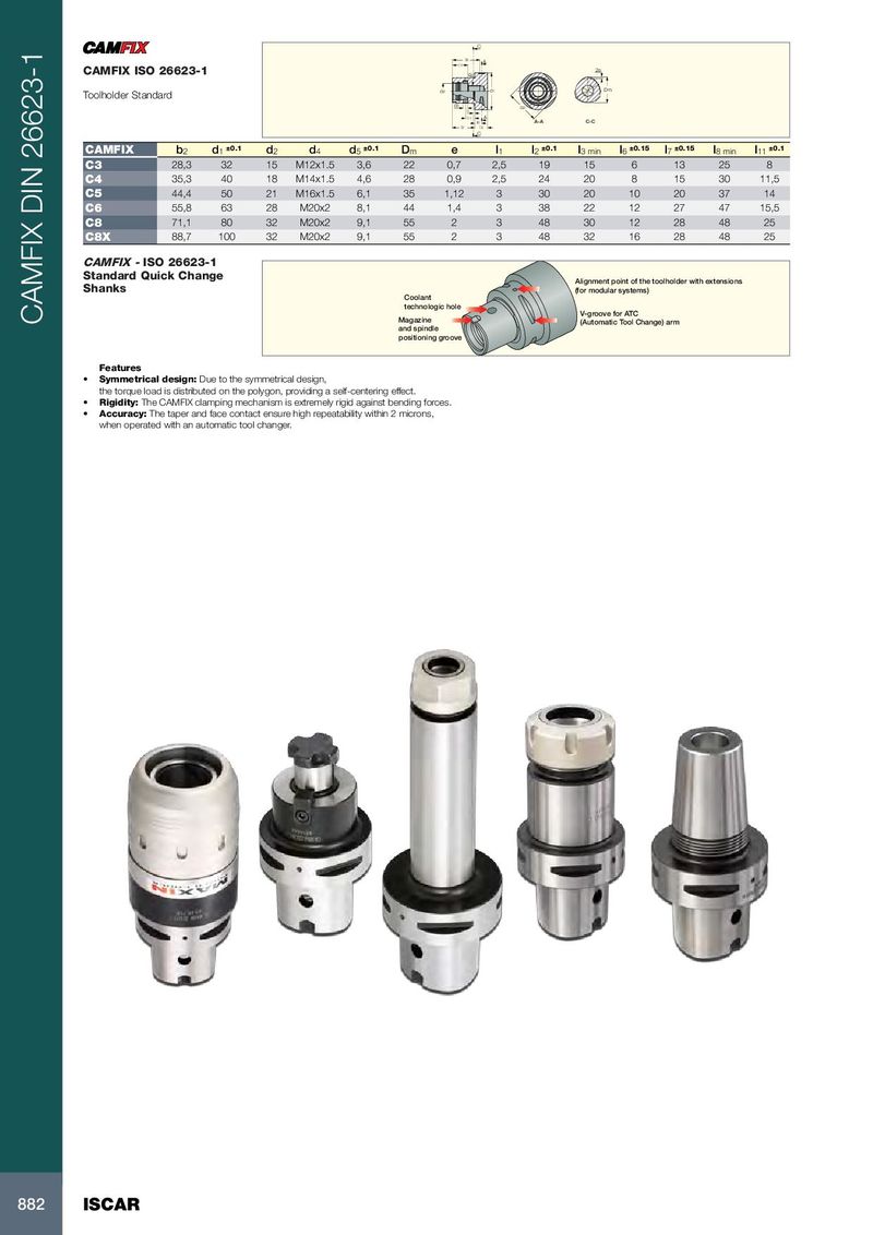
C l8 l7 A CAMFIX ISO 26623-1 d4 2e d2 d1 Dm Toolholder Standard d5 l1 b2 l11 A l6 A-A C-C l2 l3 C CAMFIX b 2 d 1 ±0.1 d 2 d 4 d 5 ±0.1 D m e l 1 l 2 ±0.1 l 3 min l 6 ±0.15 l 7 ±0.15 l 8 min l 11 ±0.1 C3 28,3 32 15 M12x1.5 3,6 22 0,7 2,5 19 15 6 13 25 8 C4 35,3 40 18 M14x1.5 4,6 28 0,9 2,5 24 20 8 15 30 11,5 C5 44,4 50 21 M16x1.5 6,1 35 1,12 3 30 20 10 20 37 14 C6 55,8 63 28 M20x2 8,1 44 1,4 3 38 22 12 27 47 15,5 C8 71,1 80 32 M20x2 9,1 55 2 3 48 30 12 28 48 25 C8X 88,7 100 32 M20x2 9,1 55 2 3 48 32 16 28 48 25 CAMFIX - ISO 26623-1 Standard Quick Change Alignment point of the toolholder with extensions Shanks (for modular systems) Coolant technologic hole V-groove for ATC CAMFIX DIN 26623-1 Magazine (Automatic Tool Change) arm and spindle positioning groove Features • Symmetrical design: Due to the symmetrical design, the torque load is distributed on the polygon, providing a self-centering effect. • Rigidity: The CAMFIX clamping mechanism is extremely rigid against bending forces. • Accuracy: The taper and face contact ensure high repeatability within 2 microns, when operated with an automatic tool changer. 882 ISCAR