Каталог Iscar вращающийся инструмент 2017 - страница 845
Навигация
 Каталог Iscar токарные пластины ISO 2022
 Каталог Iscar инструмент для фрезерования
 Каталог Iscar решения для глубокого сверления
 Каталог Iscar полирующие фрезы
 Каталог Iscar новые продукты 2018
 Каталог Iscar концевые фрезы со сменными пластинами 2022
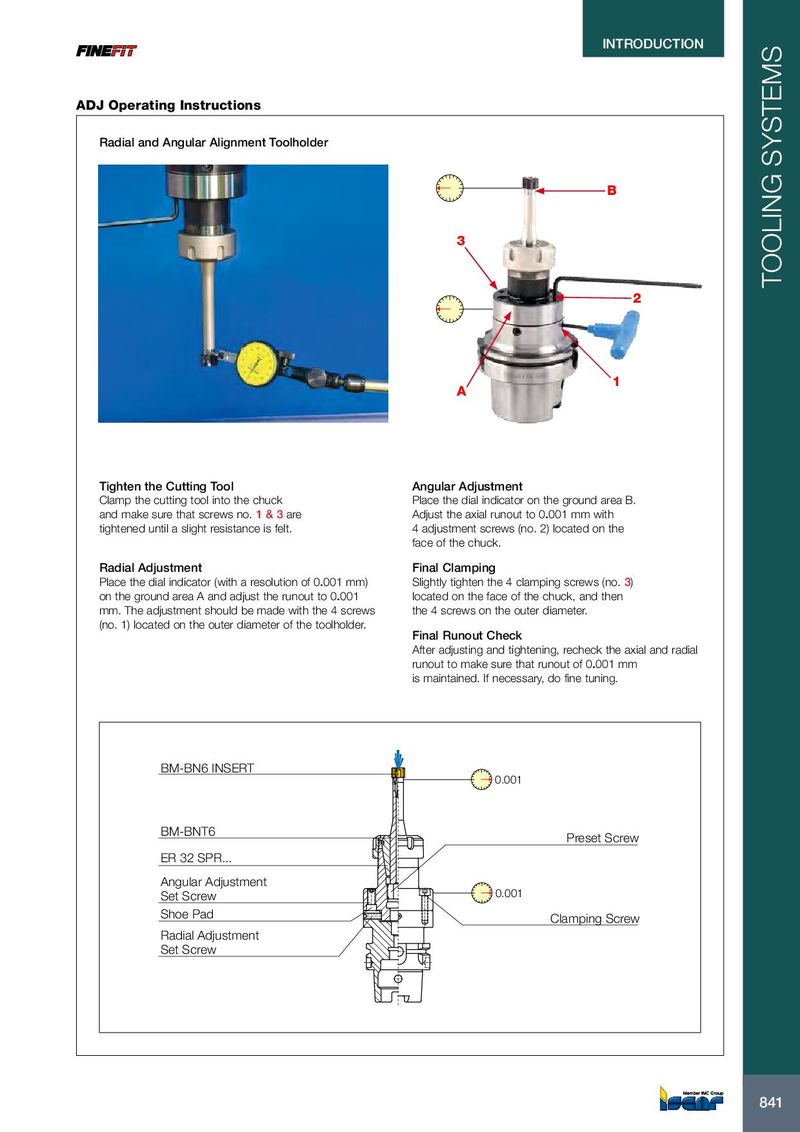
INTRODUCTION INTRODUCTION ADJ Operating Instructions Radial and Angular Alignment Toolholder B 3 TOOLING SYSTEMS 2 1 A Tighten the Cutting Tool Angular Adjustment Clamp the cutting tool into the chuck Place the dial indicator on the ground area B. and make sure that screws no. 1 & 3 are Adjust the axial runout to 0.001 mm with tightened until a slight resistance is felt. 4 adjustment screws (no. 2) located on the face of the chuck. Radial Adjustment Final Clamping Place the dial indicator (with a resolution of 0.001 mm) Slightly tighten the 4 clamping screws (no. 3) on the ground area A and adjust the runout to 0.001 located on the face of the chuck, and then mm. The adjustment should be made with the 4 screws the 4 screws on the outer diameter. (no. 1) located on the outer diameter of the toolholder. Final Runout Check After adjusting and tightening, recheck the axial and radial runout to make sure that runout of 0.001 mm is maintained. If necessary, do fine tuning. BM-BN6 INSERT 0.001 BM-BNT6 Preset Screw ER 32 SPR... Angular Adjustment Set Screw 0.001 Shoe Pad Clamping Screw Radial Adjustment Set Screw 841 841