Каталог Iscar вращающийся инструмент 2017 - страница 758
Навигация
 Каталог Iscar токарные пластины ISO 2022
 Каталог Iscar инструмент для фрезерования
 Каталог Iscar решения для глубокого сверления
 Каталог Iscar полирующие фрезы
 Каталог Iscar новые продукты 2018
 Каталог Iscar концевые фрезы со сменными пластинами 2022
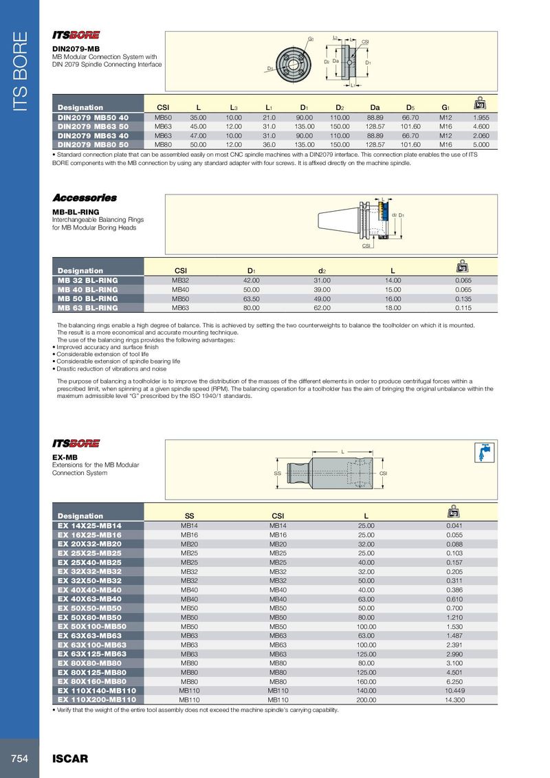
G1 L3 L CSI DIN2079-MB MB Modular Connection System with D2 Da DIN 2079 Spindle Connecting Interface D1 D5 L1 kg ITS BORE Designation CSI L L 3 L 1 D 1 D 2 Da D 5 G 1 DIN2079 MB50 40 MB50 35.00 10.00 21.0 90.00 110.00 88.89 66.70 M12 1.955 DIN2079 MB63 50 MB63 45.00 12.00 31.0 135.00 150.00 128.57 101.60 M16 4.600 DIN2079 MB63 40 MB63 47.00 10.00 31.0 90.00 110.00 88.89 66.70 M12 2.060 DIN2079 MB80 50 MB80 50.00 12.00 36.0 135.00 150.00 128.57 101.60 M16 5.000 • Standard connection plate that can be assembled easily on most CNC spindle machines with a DIN2079 interface. This connection plate enables the use of ITS BORE components with the MB connection by using any standard adapter with four screws. It is affixed directly on the machine spindle. L 60° 0 1 2 MB-BL-RING 30° g6 d2 D1 Interchangeable Balancing Rings for MB Modular Boring Heads CSI kg Designation CSI D 1 d 2 L MB 32 BL-RING MB32 42.00 31.00 14.00 0.065 MB 40 BL-RING MB40 50.00 39.00 15.00 0.065 MB 50 BL-RING MB50 63.50 49.00 16.00 0.135 MB 63 BL-RING MB63 80.00 62.00 18.00 0.115 The balancing rings enable a high degree of balance. This is achieved by setting the two counterweights to balance the toolholder on which it is mounted. The result is a more economical and accurate mounting technique. The use of the balancing rings provides the following advantages: • Improved accuracy and surface finish • Considerable extension of tool life • Considerable extension of spindle bearing life • Drastic reduction of vibrations and noise The purpose of balancing a toolholder is to improve the distribution of the masses of the different elements in order to produce centrifugal forces within a prescribed limit, when spinning at a given spindle speed (RPM). The balancing operation for a toolholder has the aim of bringing the original unbalance within the maximum admissible level “G” prescribed by the ISO 1940/1 standards. L EX-MB Extensions for the MB Modular Connection System SS CSI kg Designation SS CSI L EX 14X25-MB14 MB14 MB14 25.00 0.041 EX 16X25-MB16 MB16 MB16 25.00 0.055 EX 20X32-MB20 MB20 MB20 32.00 0.088 EX 25X25-MB25 MB25 MB25 25.00 0.103 EX 25X40-MB25 MB25 MB25 40.00 0.157 EX 32X32-MB32 MB32 MB32 32.00 0.205 EX 32X50-MB32 MB32 MB32 50.00 0.311 EX 40X40-MB40 MB40 MB40 40.00 0.386 EX 40X63-MB40 MB40 MB40 63.00 0.610 EX 50X50-MB50 MB50 MB50 50.00 0.700 EX 50X80-MB50 MB50 MB50 80.00 1.210 EX 50X100-MB50 MB50 MB50 100.00 1.530 EX 63X63-MB63 MB63 MB63 63.00 1.487 EX 63X100-MB63 MB63 MB63 100.00 2.391 EX 63X125-MB63 MB63 MB63 125.00 2.990 EX 80X80-MB80 MB80 MB80 80.00 3.100 EX 80X125-MB80 MB80 MB80 125.00 4.501 EX 80X160-MB80 MB80 MB80 160.00 6.250 EX 110X140-MB110 MB110 MB110 140.00 10.449 EX 110X200-MB110 MB110 MB110 200.00 14.300 • Verify that the weight of the entire tool assembly does not exceed the machine spindle's carrying capability. 754 ISCAR