Каталог Iscar вращающийся инструмент 2017 - страница 654
Навигация
 Каталог Iscar токарные пластины ISO 2022
 Каталог Iscar инструмент для фрезерования
 Каталог Iscar решения для глубокого сверления
 Каталог Iscar полирующие фрезы
 Каталог Iscar новые продукты 2018
 Каталог Iscar концевые фрезы со сменными пластинами 2022
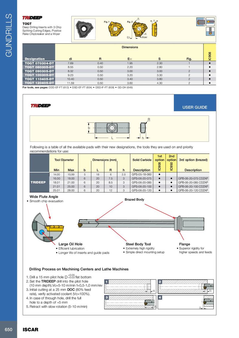
R Fig. 1 Fig. 2 S TOGT Deep Drilling Inserts with 3 Chip Splitting Cutting Edges, Positive Rake Chipbreaker and a Wiper di Eh1 Wiper Dimensions Designation di R E h1 S Fig. IC908 TOGT 070304-DT 7.69 0.40 1.95 2.30 1 • TOGT 080305-DT 8.55 0.50 2.20 2.80 1 • TOGT 090305-DT 8.32 0.50 3.00 3.00 2 • TOGT 100305-DT 9.23 0.50 3.20 3.30 2 • TOGT 110405-DT 10.40 0.50 3.40 3.80 2 • TOGT 120405-DT 11.59 0.50 3.60 4.30 2 • For tools, see pages: DDD-EF-FT (613) • DSD-EF-FT (604) • DSD-IF-FT (608) • GD-DH (649) USER GUIDE R b L h Following is a table of all the available pads with their new designations, the tools they are used on and priority recommendations for use: 1st 2nd Tool Diameter Dimensions (mm) Solid Carbide option option 3rd option (brazed) Min Max b L R h Description IC908 IC950 Description 14.00 15.99 5 18 6 2.5 GPS-05-18-060 • 16.00 18.00 6 20 7.5 3 GPS-06-20-075 • • GPB-06-20-075 CDZAP TRIDEEP 18.01 21.00 6 20 8.5 3 GPS-06-20-085 • • GPB-06-20-085 CDZAP 21.01 25.00 6 20 10 3 GPS-06-20-100 • • GPB-06-20-100 CDZAP 25.01 28.00 6 20 12 3 GPS-06-20-120 • • GPB-06-20-120 CDZAP Wide Flute Angle GUNDRILLS Brazed Body • Smooth chip evacuation Large Oil Hole Steel Body Tool Flange • Efficient lubrication • Extremely high rigidity • Superior rigidity for • Longer life of inserts and guide pads • Simple direct mounting setup higher speeds and feeds Drilling Process on Machining Centers and Lathe Machines +0.05 1. Drill a 15 mm pilot hole D +0.03 flat bottom 2. Set the TRIDEEP drill into the pilot hole 1 2 (10 mm depth).Vc=5-10 m/min f=0.5-1.0 mm/rev 3. Initial cutting at a 25 mm DOC (80% feed 15 10 rate), verify activated coolant (Vc=100%). 4. In case of through hole, drill the full 3 4 hole to a depth of +5 mm 5. Retract with slow rotation (5-10 m/min) 25 5 650 ISCAR