Каталог Iscar вращающийся инструмент 2017 - страница 601
Навигация
 Каталог Iscar токарные пластины ISO 2022
 Каталог Iscar инструмент для фрезерования
 Каталог Iscar решения для глубокого сверления
 Каталог Iscar полирующие фрезы
 Новые режущие инструменты Iscar 2026
 Каталог Iscar новые продукты 2018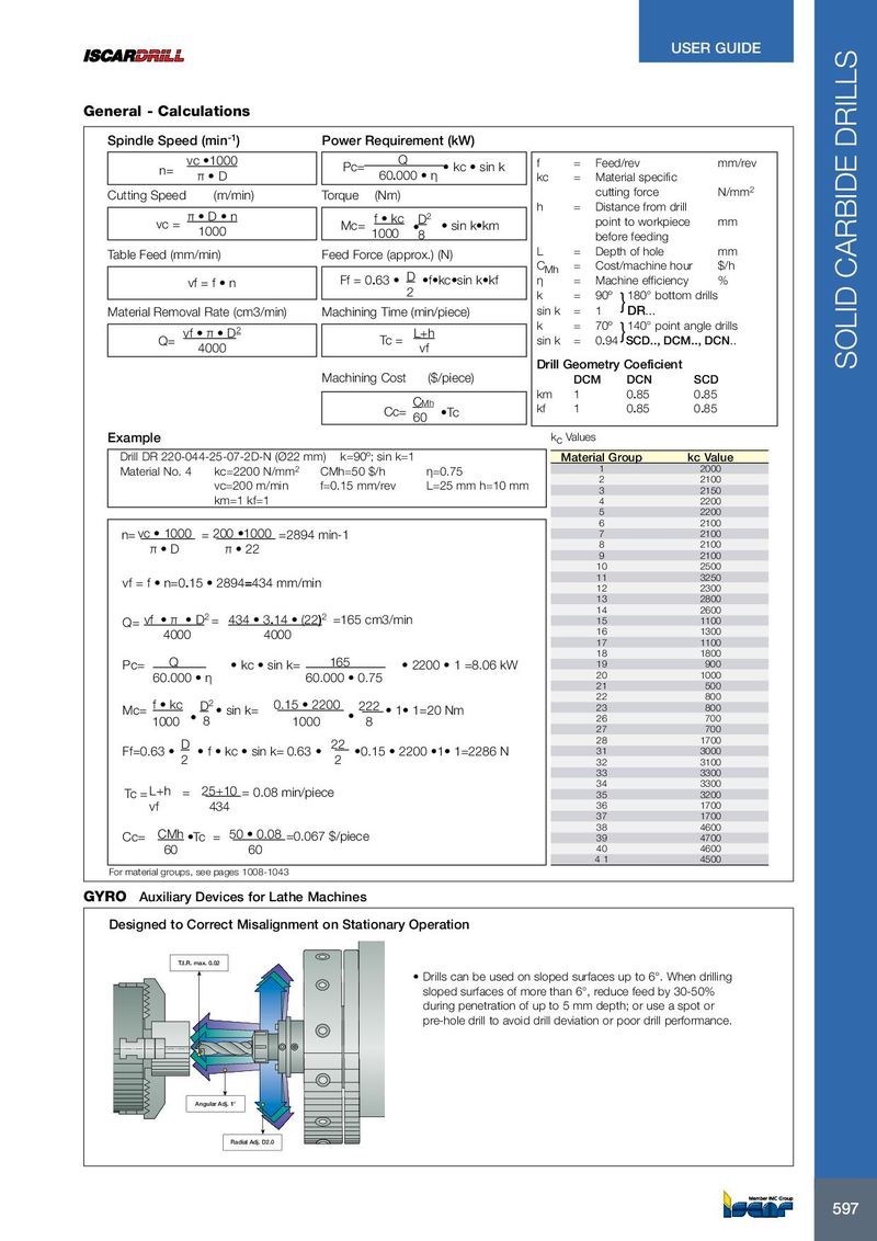
General - Calculations
Spindle Speed (min-1) Power Requirement (kW)
vc •1000 Q f = Feed/rev mm/rev
n= Pc= kc sin k
π D 60.000 η kc = Material specific
Cutting Speed (m/min) Torque (Nm) cutting force N/mm2
h = Distance from drill
π D n f kc D2 point to workpiece mm
vc = Mc= sin k•km
1000 1000 8 before feeding
Table Feed (mm/min) Feed Force (approx.) (N) L = Depth of hole mm
CMh = Cost/machine hour $/h
Ff = 0.63 D •f•kc•sin k•kf η = Machine efficiency %
vf = f n
2 k = 90º }180° bottom drills
Material Removal Rate (cm3/min) Machining Time (min/piece) sin k = 1 DR...
k = 70º }140° point angle drills vf π D2 L+h
Q= Tc = sin k = 0.94 SCD.., DCM.., DCN..
4000 vf Drill Geometry Coeficient
Machining Cost ($/piece) DCM DCN SCD
km 1 0.85 0.85
CMh
Cc= •Tc kf 1 0.85 0.85
60 Example kc Values
Drill DR 220-044-25-07-2D-N (Ø22 mm) k=90º; sin k=1 Material Group kc Value
| Material No. 4 | kc=2200 N/mm2 | CMh=50 $/h | η=0.75 | 1 | 2000 |
| vc=200 m/min | f=0.15 mm/rev | L=25 mm h=10 mm | 2 | 2100 |
3 2150
km=1 kf=1 4 2200
5 2200 6 2100
| n= vc 1000 | = 200 •1000 | =2894 min-1 | 7 | 2100 | ||
| π D | π 22 | 8 | 2100 |
9 2100 10 2500
vf = f n=0.15 2894=434 mm/min 11 3250
12 2300 13 2800 14 2600
| Q= vf π D2 = 434 3.14 (22)2 =165 cm3/min | 15 | 1100 | ||
| 4000 | 4000 | 16 | 1300 |
17 1100 18 1800
| Pc= | Q | kc sin k= | 165 | 2200 1 =8.06 kW | 19 | 900 | |
| 60.000 η | 60.000 0.75 | 20 | 1000 |
21 500
| f kc | 0.15 2200 | 22 | 800 | ||||||
| Mc= | D2 sin k= | 222 1• 1=20 Nm | 23 | 800 | |||||
| 1000 | 8 | 1000 | 8 | 26 | 700 |
27 700
| D | 22 | 28 | 1700 | |||
| Ff=0.63 | f kc sin k= 0.63 | •0.15 2200 •1• 1=2286 N | 31 | 3000 | ||
| 2 | 2 | 32 | 3100 |
33 3300
| L+h | 25+10 | 34 | 3300 | |||
| Tc = | = | = 0.08 min/piece | 35 | 3200 | ||
| vf | 434 | 36 | 1700 |
37 1700
| CMh | 50 0.08 | 38 | 4600 | ||||
| Cc= | •Tc = | =0.067 $/piece | 39 | 4700 | |||
| 60 | 60 | 40 | 4600 |
4 1 4500 For material groups, see pages 1008-1043
GYRO Auxiliary Devices for Lathe Machines
Designed to Correct Misalignment on Stationary Operation
T.I.R. max. 0.02
- Drills can be used on sloped surfaces up to 6°. When drilling sloped surfaces of more than 6°, reduce feed by 30-50% during penetration of up to 5 mm depth; or use a spot or pre-hole drill to avoid drill deviation or poor drill performance.
Angular Adj. 1°
Radial Adj. D2.0