Каталог Iscar вращающийся инструмент 2017 - страница 513
Навигация
 Каталог Iscar токарные пластины ISO 2022
 Каталог Iscar инструмент для фрезерования
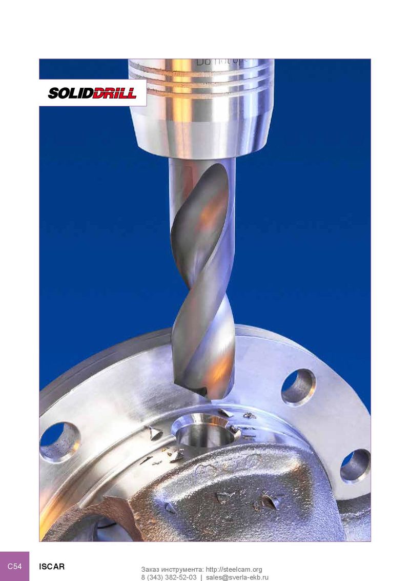 Каталог Iscar решения для глубокого сверления
 Каталог Iscar полирующие фрезы
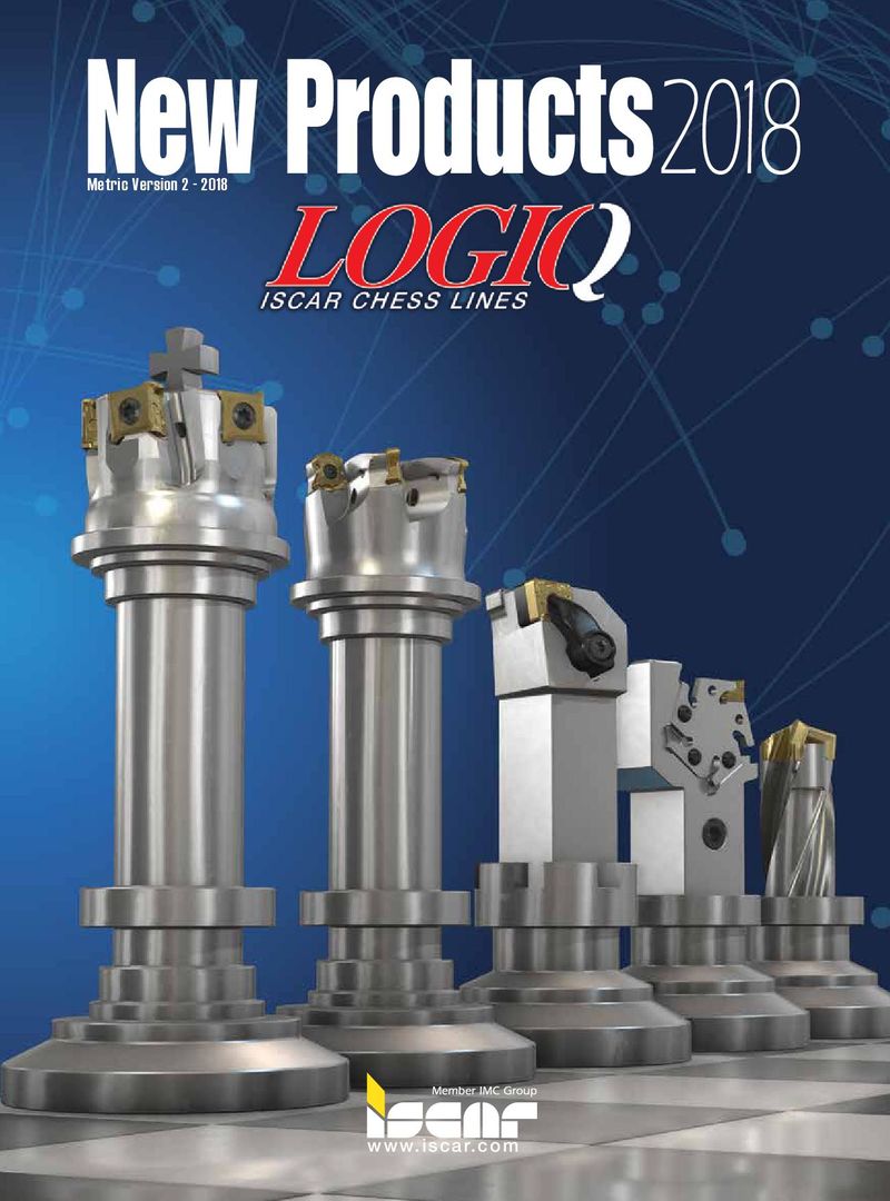 Каталог Iscar новые продукты 2018
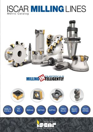 Каталог Iscar концевые фрезы со сменными пластинами 2022
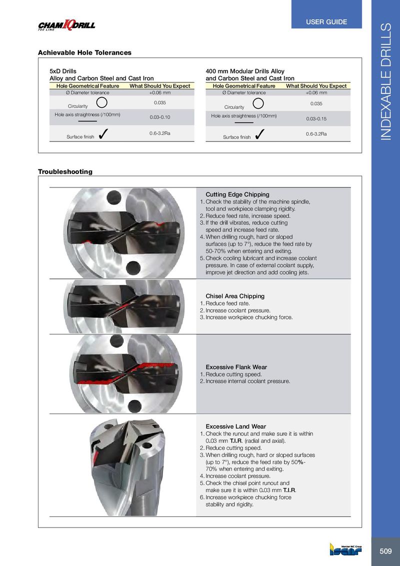
USER GUIDE Achievable Hole Tolerances 5xD Drills 400 mm Modular Drills Alloy Alloy and Carbon Steel and Cast Iron and Carbon Steel and Cast Iron Hole Geometrical Feature What Should You Expect Hole Geometrical Feature What Should You Expect Ø Diameter tolerance +0.06 mm Ø Diameter tolerance +0.06 mm 0.035 0.035 Circularity Circularity Hole axis straightness (/100mm) 0.03-0.10 Hole axis straightness (/100mm) 0.03-0.15 0.6-3.2Ra 0.6-3.2Ra Surface finish ✓ Surface finish ✓ INDEXABLE DRILLS Troubleshooting Cutting Edge Chipping 1. Check the stability of the machine spindle, tool and workpiece clamping rigidity. 2. Reduce feed rate, increase speed. 3. If the drill vibrates, reduce cutting speed and increase feed rate. 4. When drilling rough, hard or sloped surfaces (up to 7°), reduce the feed rate by 50-70% when entering and exiting. 5. Check cooling lubricant and increase coolant pressure. In case of external coolant supply, improve jet direction and add cooling jets. Chisel Area Chipping 1. Reduce feed rate. 2. Increase coolant pressure. 3. Increase workpiece chucking force. Excessive Flank Wear 1. Reduce cutting speed. 2. Increase internal coolant pressure. Excessive Land Wear 1. Check the runout and make sure it is within 0.03 mm T.I.R. (radial and axial). 2. Reduce cutting speed. 3. When drilling rough, hard or sloped surfaces (up to 7°), reduce the feed rate by 50%- 70% when entering and exiting. 4. Increase coolant pressure. 5. Check the chisel point runout and make sure it is within 0.03 mm T.I.R. 6. Increase workpiece chucking force stability and rigidity. 509 509