Каталог Iscar токарный инструмент 2017 - страница 468
Навигация
 Каталог Iscar резьбонарезные фрезы
 Каталог Iscar инструмент для обработки алюминиевых колёс
 Каталог Iscar державки и пластины для нарезания резьбы 2022
 Каталог Iscar расточные системы 2022
 Каталог Iscar высокоточные развертки и метчики 2022
 Каталог Iscar вращающийся инструмент 2017
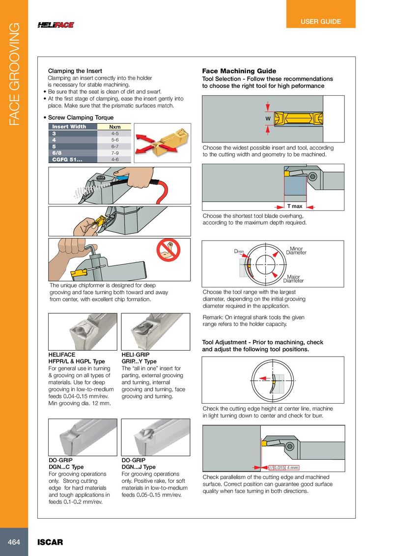
USER GUIDE Clamping the Insert Face Machining Guide Clamping an insert correctly into the holder Tool Selection - Follow these recommendations is necessary for stable machining. to choose the right tool for high peformance • Be sure that the seat is clean of dirt and swarf. • At the first stage of clamping, ease the insert gently into place. Make sure that the prismatic surfaces match. • Screw Clamping Torque W FACE GROOVING Insert Width Nxm 3 4-5 4 5-6 5 6-7 Choose the widest possible insert and tool, according 6/8 7-9 to the cutting width and geometry to be machined. CGFG 51... 4-6 T max Choose the shortest tool blade overhang, according to the maximum depth required. Minor Dmin Diameter Major Diameter The unique chipformer is designed for deep grooving and face turning both toward and away Choose the tool range with the largest from center, with excellent chip formation. diameter, depending on the initial grooving diameter required in the application. Remark: On integral shank tools the given range refers to the holder capacity. Tool Adjustment - Prior to machining, check and adjust the following tool positions. HELIFACE HELI-GRIP HFPR/L & HGPL Type GRIP...Y Type For general use in turning The “all in one” insert for & grooving on all types of parting, external grooving materials. Use for deep and turning, internal grooving in low-to-medium grooving and turning, face feeds 0.04-0.15 mm/rev. grooving and turning. Min grooving dia. 12 mm. Check the cutting edge height at center line, machine in light turning down to center and check for burr. DO-GRIP DO-GRIP DGN...C Type DGN...J Type // 0.015 4 mm For grooving operations For grooving operations Check parallelism of the cutting edge and machined only. Strong cutting only. Positive rake, for soft surface. Correct position can guarantee good surface edge for hard materials materials in low-to-medium quality when face turning in both directions. and tough applications in feeds 0.05-0.15 mm/rev. feeds 0.1-0.2 mm/rev. 464 464 ISCAR ISCAR