Каталог Iscar токарные пластины ISO 2022 - страница 2
Навигация
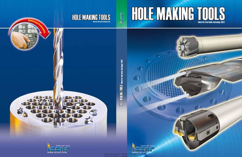 Каталог Iscar инструмент для обработки отверстий
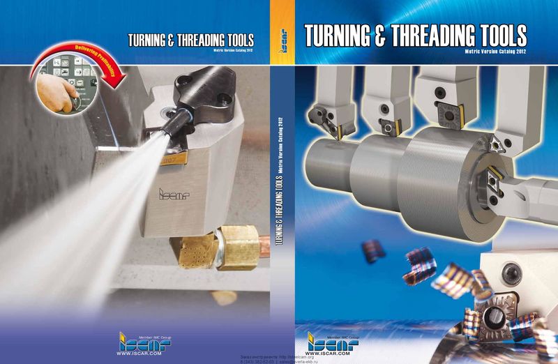 Каталог Iscar инструмент для токарной обработки
 Каталог Iscar концевые фрезы со сменными пластинами 2022
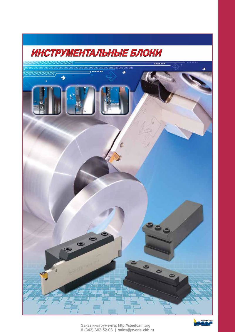 Каталог Iscar инструментальные блоки
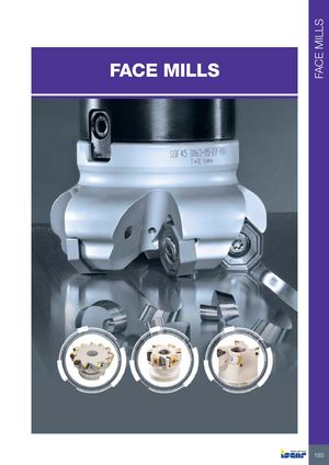 Каталог Iscar торцевые фрезы 2022
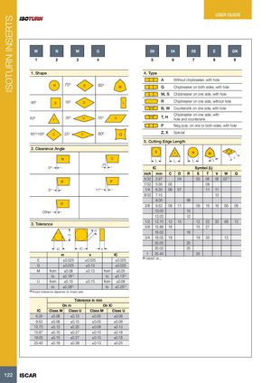
ISOTURN INSERTS USER GUIDE W N M G 08 04 08 E GN 1 2 3 4 5 6 7 8 9 1. Shape 4. Type A Without chipbreaker, with hole R 75º E 80º W G Chipbreaker on both sides, with hole M, S Chipbreaker on one side, with hole 90º S 55º D L R Chipbreaker on one side, without hole B, W Countersink on one side, with hole 60º 35ºT V 55º K T, H Chipbreaker on one side, withhole and countersink P Neg./pos. on one or both sides, with hole 80º/100º C 25º Y 80º Q Z, X Special 5. Cutting Edge Length 2. Clearance Angle C L L L L L 7º 0º IC Symbol (L) inch mm C D R S T V W Q 5/32 3.97 04 03 06 06 02(1) 7/32 5.56 05 09 5º 11º 1/4 6.35 06 07 11 11 9/32 7.15 12 8.00 08 3/8 9.52 09 11 09 16 16 06 09 Other 10.00 10 12.00 12 3. Tolerance 1/2 12.70 12 15 12 22 22 08 12 5/8 15.88 16 15 27 m 16.00 16 m 3/4 19.05 19 19 33 13 20.00 20 IC IC s 25.00 25 m s IC 1 25.40 25 E ±0.025 ±0.025 ±0.025 (1) WBMT 06... G ±0.025 ±0.13 ±0.025 M from ±0.08 ±0.13 from ±0.05 to ±0.18(1) to ±0.13(1) U from ±0.13 ±0.13 from ±0.08 to ±0.38(1) to ±0.25(1) (1) Exact tolerance depends on insert size Tolerance in mm On m On IC IC Class M Class U Class M Class U 6.35 ±0.08 ±0.13 ±0.05 ±0.08 9.52 ±0.08 ±0.13 ±0.05 ±0.08 12.70 ±0.13 ±0.20 ±0.08 ±0.13 15.87 ±0.15 ±0.27 ±0.10 ±0.18 19.05 ±0.15 ±0.27 ±0.10 ±0.18 25.40 ±0.18 ±0.38 ±0.13 ±0.25 122 ISCAR