Каталог Iscar сверла со сменной режущей частью 2022 - страница 140
Навигация
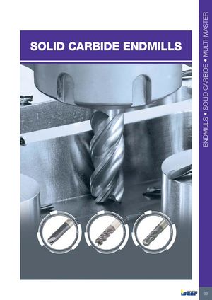 Каталог Iscar монолитные фрезы 2022
 Каталог Iscar токарный инструмент
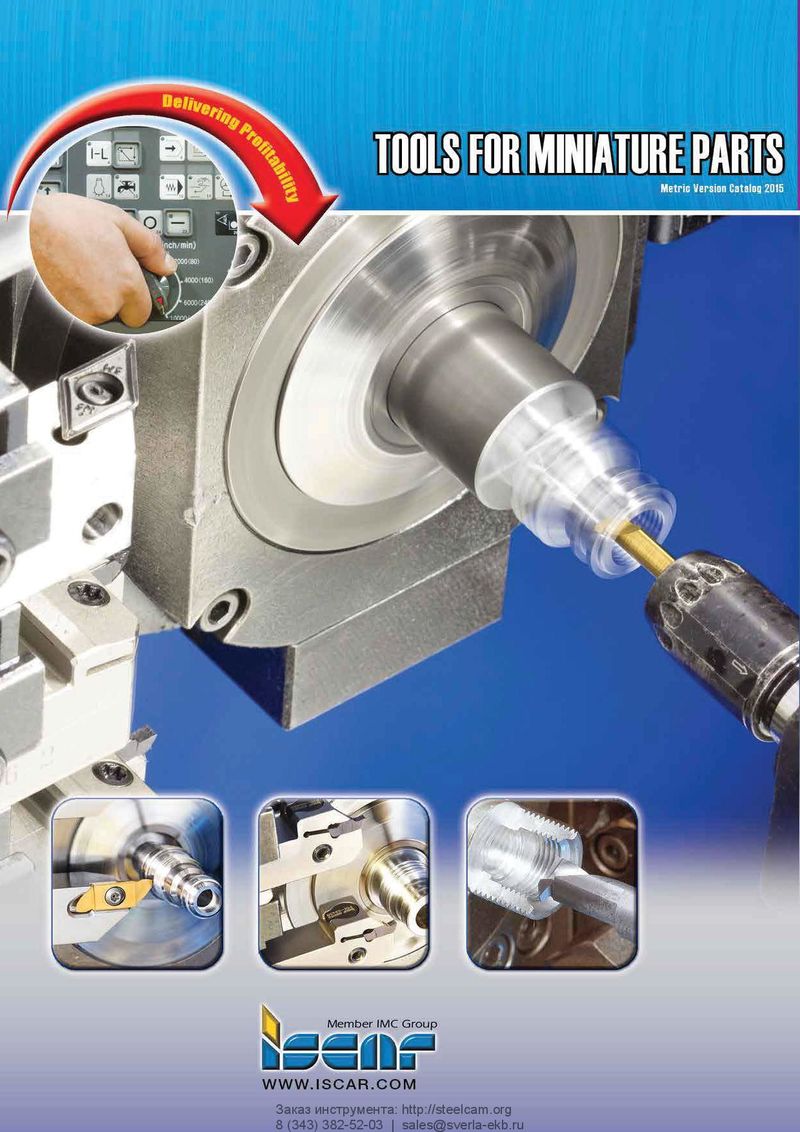 Каталог Iscar инструмент для мелкоразмерной обработки
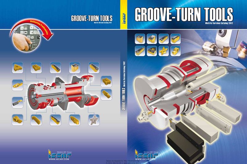 Каталог Iscar токарный инструмент для нарезания канавок
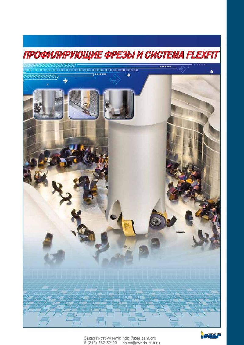 Каталог Iscar полирующие фрезы
 Каталог Iscar дисковые фрезы и фрезерные пластины 2022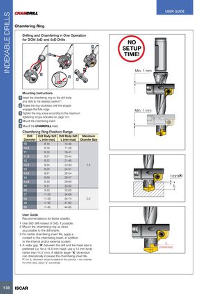
Chamfering Ring
Drilling and Chamfering in One Operation
for DCM 3xD and 5xD Drills
3
NO
4 SETUP
TIME!
1 2
Min. 1 mm
5
Mounting Instructions 1 Insert the chamfering ring on the drill body and slide to the desired position(1). 2 Rotate the ring clockwise until the stopper engages the flute edge. Min. 1 mm 3 Tighten the ring screw according to the maximum tightening torque indicated on page 137. 4 Mount the chamfering insert. 5 Mount the CHAMDRILL head.
Chamfering Ring Position Range
| Drill | Drill Body 3xD | Drill Body 5xD | Maximum | |
| Diameter | L (min-max) | L (min-max) | Chamfer Size |
| 10 | 8-16 | 15-36 |
| 10.5 | 8-18 | 17-39 |
| 11 | 8-19 | 18-41 |
| 11.5 | 8-21 | 20-44 |
| 12 | 8-22 | 21-46 |
| 12.5 | 8-24 | 1.5 23-49 |
| 13 | 8-25 | 24-51 |
| 13.5 | 8-27 | 26-54 |
| 14 | 9-29 | 28-57 |
| 14.5 | 9-30 | 29-60 |
| 15 | 9-31 | 30-60 |
| 16 | 9-33 | 32-65 |
| 17 | 11-35 | 34-69 |
| 18 | 11-38 | 2.0 34-74 |
| 19 | 11-42 | 41-80 |
| 20 | 11-45 | 44-85 |
User Guide Recommendations for better stability: 1 Use 3xD drill instead of 5xD, if possible. 2 Mount the chamfering ring as close
as possible to the drill shank. 3 For better chamfering insert life, apply a coolant to the chamfering insert, in addition to the internal and/or external coolant. 4 A wider gap “X” between the drill and the head size is preferred (i.e. for a 14.6 mm head, use a 14 mm body rather than 14.5 mm). A slightly larger “X” dimension can dramatically increase the chamfering insert life. (1) The “L” dimension shown is relative to the common 1 mm chamfer. For other sizes, adjust “L” accordingly.
1mm
(1)
L
X (maximize)