Каталог Iscar сверла ружейные и для глубокого сверления 2022 - страница 78
Навигация
 Каталог Iscar новые продукты 2018
 Каталог Iscar полирующие фрезы
 Каталог Iscar инструмент для фрезерования
 Каталог Iscar инструмент для нарезания резьбы
 Каталог Iscar токарные державки ISO 2022
 Фрезерные инструменты Iscar 2026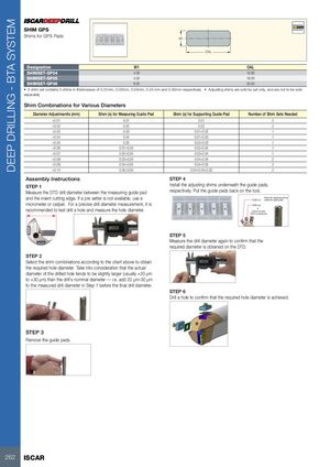
SHIM GPS
Shims for GPS Pads
W1
OAL
| Designation | W1 | OAL |
| SHIMSET-GP04 | 4.00 | 15.90 |
| SHIMSET-GP05 | 5.00 | 18.00 |
| SHIMSET-GP06 | 6.00 | 20.00 |
- 5 shim set contains 5 shims in thicknesses of 0.01mm, 0.02mm, 0.03mm, 0.04 mm and 0.05mm respectively
- Adjusting shims are sold by set only, and are not to be sold
separately
Shim Combinations for Various Diameters
| Diameter Adjustmemts (mm) | Shim (s) for Measuring Guide Pad | Shim (s) for Supporting Guide Pad | Number of Shim Sets Needed |
| +0.01 | 0.01 | 0.01 | 2 |
| +0.02 | 0.02 | 0.02 | 2 |
| +0.03 | 0.03 | 0.01+0.02 | 1 |
| +0.04 | 0.04 | 0.01+0.03 | 1 |
| +0.05 | 0.05 | 0.02+0.03 | 1 |
| +0.06 | 0.01+0.05 | 0.02+0.04 | 1 |
| +0.07 | 0.02+0.05 | 0.03+0.04 | 1 |
| +0.08 | 0.03+0.05 | 0.04+0.04 | 2 |
| +0.09 | 0.04+0.05 | 0.04+0.05 | 2 |
| +0.10 | 0.05+0.05 | 0.04+0.04+0.02 | 2 |
Assembly Instructions STEP 4
STEP 1 Install the adjusting shims underneath the guide pads, Measure the DTD drill diameter between the measuring guide pad respectively. Put the guide pads back on the tool.
and the insert cutting edge. If a pre setter is not available, use a
micrometer or caliper. For a precise drill diameter measurement, it is
recommended to test drill a hole and measure the hole diameter.
STEP 2
Select the shim combinations according to the chart above to obtain
the required hole diameter. Take into consideration that the actual
diameter of the drilled hole tends to be slightly larger (usually +20 μm
to +30 μm) than the drill’s nominal diameter — i.e. add 20 μm-30 μm
to the measured drill diameter in Step 1 before the final drill diameter.
STEP 5
Measure the drill diameter again to confirm that the
required diameter is obtained on the DTD.
STEP 6
Drill a hole to confirm that the required hole diameter is achieved.
STEP 3
Remove the guide pads.