Каталог Iscar обработка канавок 2022 - страница 49
Навигация
 Каталог Iscar монолитные концевые фрезы и система multi-master
 Фрезерные инструменты Iscar 2026
 Каталог Iscar сверла ружейные и для глубокого сверления 2022
 Каталог Iscar токарные державки ISO 2022
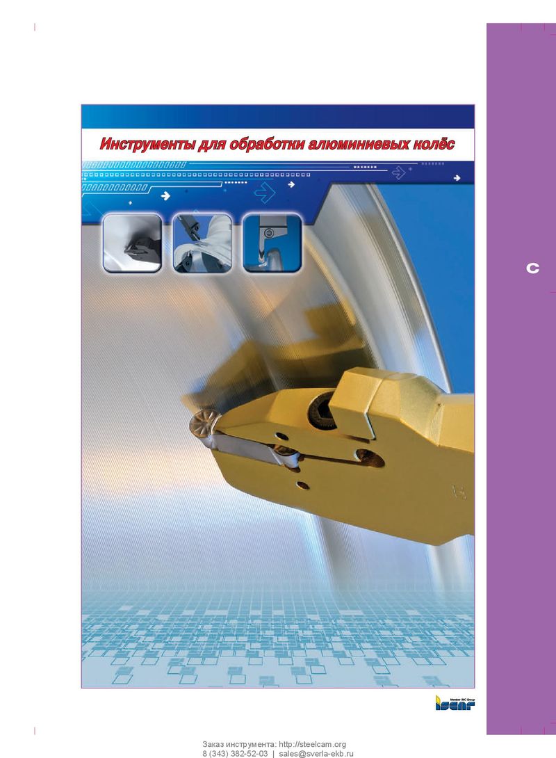 Каталог Iscar инструмент для обработки алюминиевых колёс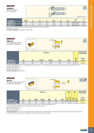
GHMUR/L
External Holders for
45° Undercutting OAL 1.5 WF 45° B CWX Right-hand shown
| Designation | CWX(1) | H | HF | B | OAL | LH | WF | ||
| GHMUR/L 16 | 4.80 | 16.0 | 16.0 | 16.0 | 112.00 | 25.0 | 19.00 | SR M6X16 DIN912 | HW 5.0 |
| GHMUR/L 20 | 6.40 | 20.0 | 20.0 | 20.0 | 122.00 | 25.0 | 23.00 | SR M6X16 DIN912 | HW 5.0 |
| GHMUR/L 25 | 6.40 | 25.0 | 25.0 | 25.0 | 137.00 | 25.0 | 28.00 | SR M6X16 DIN912 | HW 5.0 |
- For D>100 mm, GIP/GIF inserts can be used (clearance types UN, D or G are not required).
(1) Maximum cutting width
For inserts, see pages: GIMY-UN (303) GIP-UN (303)
±0.025
GIMY-UN
Utility Single-Ended Inserts 7°
for External Undercutting
15 Ref. CW BW RE
Dimensions Recommended
Machining Data
f groove
| Designation | CW | RE | CWTOL(1) | RETOL(2) | BW | CDX(3) | (mm/rev) | |
| GIMY 315-UN | 3.00 | 1.50 | 0.05 | 0.050 | 2.40 | 2.00 | • | 0.05-0.15 |
| GIMY 420-UN | 4.00 | 2.00 | 0.05 | 0.050 | 3.20 | 2.50 | • | 0.05-0.15 |
- For 45° undercutting on D 100 mm, regular GIMY inserts may be used.
- For cutting speed recommendations and user guide, see pages 419-428, 432-436
(1) Cutting width tolerance (+/-) (2) Corner radius tolerance (+/-) (3) Cutting depth maximum
For tools, see pages: GHMUR/L (303)
±0.025
GIP-UN
Precision Double-Ended Inserts 7° for External Undercutting 5 15.3 Ref. CW RE
Recommended
Dimensions Tough 1 Hard Machining Data
f groove
| Designation | CW | RE | CWTOL(1) | RETOL(2) | DMIN | BW | CDX(3) | (mm/rev) | ||||
| GIP 3.00-1.50UN | 3.00 | 1.50 | 0.05 | 0.050 | 35.00 | 2.40 | 4.00 | • | • | • | • | 0.05-0.15 |
| GIP 4.00-2.0UN | 4.00 | 2.00 | 0.05 | 0.050 | 35.00 | 3.20 | 4.00 | • | • | 0.05-0.15 |
- Not recommended for turning.
- For undercutting at 45° and D100 mm, other GIP inserts apply as well
- For cutting speed recommendations and user guide, see pages 419-428, 432-436
(1) Cutting width tolerance (+/-) (2) Corner radius tolerance (+/-) (3) Cutting depth maximum
For tools, see pages: C#-GHDR/L (274) CGHN-DG (283) CGPAD (281) CGPAD-JHP (282) GHDR/L (short pocket) (275) GHDR/L-JHP (short pocket) (276)
- GHDR/L-JHP-MC (short pocket) (277)
- GHMPR/L (273)
- GHMR/L (273)
- GHMUR/L (303)