Каталог Iscar обработка канавок 2022 - страница 33
Навигация
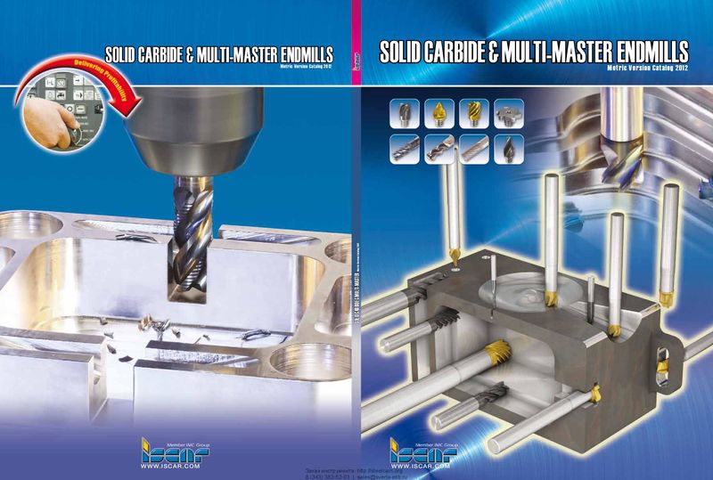 Каталог Iscar монолитные концевые фрезы и система multi-master
 Фрезерные инструменты Iscar 2026
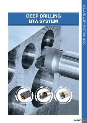 Каталог Iscar сверла ружейные и для глубокого сверления 2022
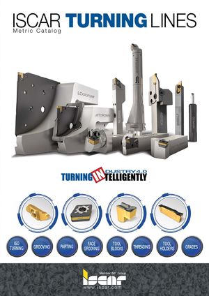 Каталог Iscar токарные державки ISO 2022
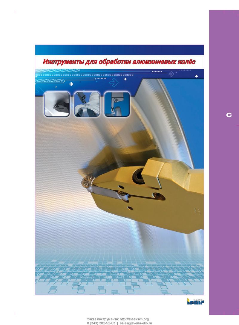 Каталог Iscar инструмент для обработки алюминиевых колёс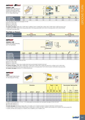
| GADR/L-JHP Adapters with High-Pressure Coolant Channels Carrying Groove-Turn Inserts for up to | OAL OAH CDX HF | WB2 WB | Bar Max | ||||
| 25 mm Deep Machining | WF CWN-CWX | Righ | t-hand shown | ||||
| Designation | CWN(1) CWX(2) | CDX(3) | WB HF | OAH | OAL | WB2 | WF |
| GADR/L 8-JHP | 6.60 8.30 | 25.50 | 6.00 32.0 | 42.0 | 63.00 | 17.0 | 14.00 |
| GADR/L 10-JHP | 8.60 10.30 | 25.50 | 7.40 32.0 | 42.0 | 63.00 | 17.7 | 14.00 |
- For user guide and accessories see pages 419-438
(1) Minimum cutting width (2) Maximum cutting width (3) Cutting depth maximum
For inserts, see pages: GDMA (300) GDMF (288) GDMM-CC (583) GDMN (289) GDMU (290) GDMY (289) GDMY (full radius) (291)
- GDMY-F (291)
- GDPY (293)
- GIA-K (long pocket) (299)
- GIF (long pocket) (298)
- GIF-E (W=8,10 full radius) (294)
- GIF-E (W=8,10) (292)
- GIPA/GIDA 8 (full radius) (302)
Flow Rate vs. Pressure
| Designation | 70 Bar Flow Rate(liters/min) | 100 Bar Flow Rate(liters/m | in) | 140 Bar Flow Rate(liters/min) | |
| GADR/L-JHP | 15-17 | 23-25 | 27-29 | ||
| CGHN-8-10D Heavy Duty Deep Grooving and Turning Blades | CWN-CWX | OHX OAL | 150˚ H HF WB |
| Designation | CWN(1) | CWX(2) | OHX(3) | WB | HF | H | OAL | ||
| CGHN 52-8D | 8.00 | 8.30 | 50.0 | 7.40 | 45.0 | 52.6 | 190.00 | SR 76-1637 | HW 4.0 |
| CGHN 53-8D | 8.00 | 8.30 | 70.0 | 7.40 | 45.0 | 52.6 | 260.00 | SR 76-1637 | HW 4.0 |
| CGHN 52-10D | 10.00 | 11.00 | 70.0 | 9.20 | 45.0 | 52.6 | 190.00 | SR 76-1289 | HW 5.0 |
| CGHN 53-10D | 10.00 | 11.00 | 100.0 | 9.20 | 45.0 | 52.6 | 260.00 | SR 76-1289 | HW 5.0 |
- For user guide, see pages 419-428, 432-436
(1) Minimum cutting width (2) Maximum cutting width (3) Minimum overhang When using a double-ended insert, grooving depth is limited by the insert
For inserts, see pages: GDMF (288) GDMN (289) GDMU (290) GDMY (289) GDMY (full radius) (291) GDMY-F (291) GDPY (293)
- GIA-K (long pocket) (299)
- GIF (long pocket) (298)
- GIF-E (W=8,10 full radius) (294)
- GIF-E (W=8,10) (292)
- GIPA/GIDA 8 (full radius) (302)
For holders, see pages: SGTBK (617) SGTBU/SGTBN (616)
GIMT
Utility Single-Ended Inserts
for Grooving and Turning
±0.1 7º 15.3Ref 5 CW BW RE
| Dimensions | Toug | h1 | Hard | Recomm | ended Machi | ning Data | |||||||
| Designation | CW | RE | CWTOL(1) | RETOL(2) | BW | IC830 | IC8250 | IC808 | IC07 | IC806 | ap (mm) | f turn (mm/rev) | f groove (mm/rev) |
| GIMT 302 | 3.00 | 0.20 | 0.05 | 0.050 | 2.40 | • | • | • | • | • | 0.50-1.80 | 0.10-0.22 | 0.07-0.15 |
| GIMT 304 | 3.00 | 0.40 | 0.05 | 0.050 | 2.40 | • | • | • | • | • | 0.50-1.80 | 0.10-0.22 | 0.07-0.15 |
| GIMT 402 | 4.00 | 0.20 | 0.05 | 0.050 | 3.40 | • | • | • | • | • | 0.50-2.40 | 0.15-0.25 | 0.09-0.20 |
| GIMT 404 | 4.00 | 0.40 | 0.05 | 0.050 | 3.40 | • | • | • | • | • | 0.50-2.40 | 0.15-0.25 | 0.09-0.20 |
| GIMT 508 | 5.00 | 0.80 | 0.05 | 0.050 | 4.00 | • | • | • | • | • | 1.00-3.00 | 0.20-0.35 | 0.11-0.22 |
| GIMT 608 | 6.00 | 0.80 | 0.05 | 0.050 | 5.00 | • | • | • | • | • | 1.00-3.60 | 0.22-0.40 | 0.13-0.25 |
- DMIN for internal applications = 70 mm
- For cutting speed recommendations and user guide, see pages 419-428, 432-436
(1) Cutting width tolerance (+/-) (2) Corner radius tolerance (+/-)
For tools, see pages: Anti-Vibration Blades (284) C#-GHDR/L (274) CGHN 26-M (356) CGHN 32-DGM (358) CGHN 32-M (357)
- CGHN-D (283)
- CGHN-DG (283)
- CGHN-S (282)
- CGPAD (281)
- CGPAD-JHP (282)
- GHDR/L (short pocket) (275)
- GHDR/L-JHP (short pocket) (276)
- GHDR/L-JHP-MC (short pocket) (277)
- GHGR/L (278)
- GHMPR/L (273)
- GHMR/L (273)