Каталог Iscar инструмент для мелкоразмерной обработки - страница 39
Навигация
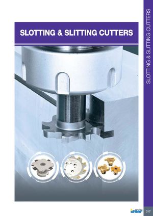 Каталог Iscar дисковые фрезы и фрезерные пластины 2022
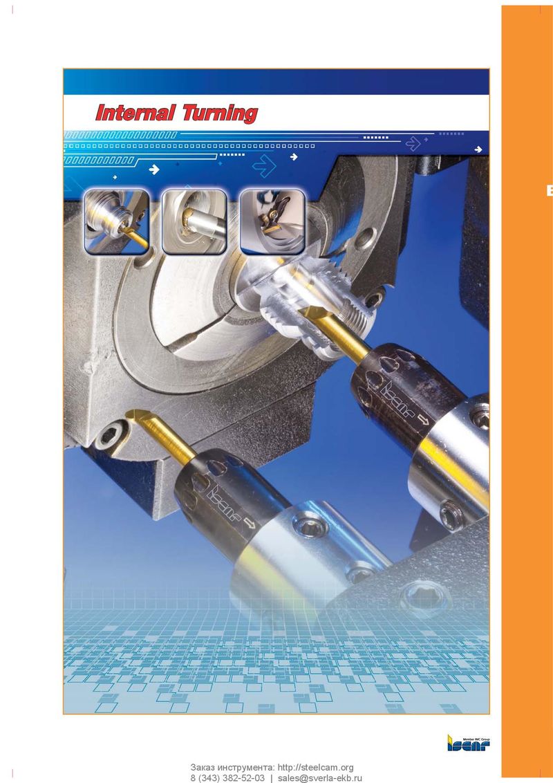 Каталог Iscar инструмент для внутренней обработки
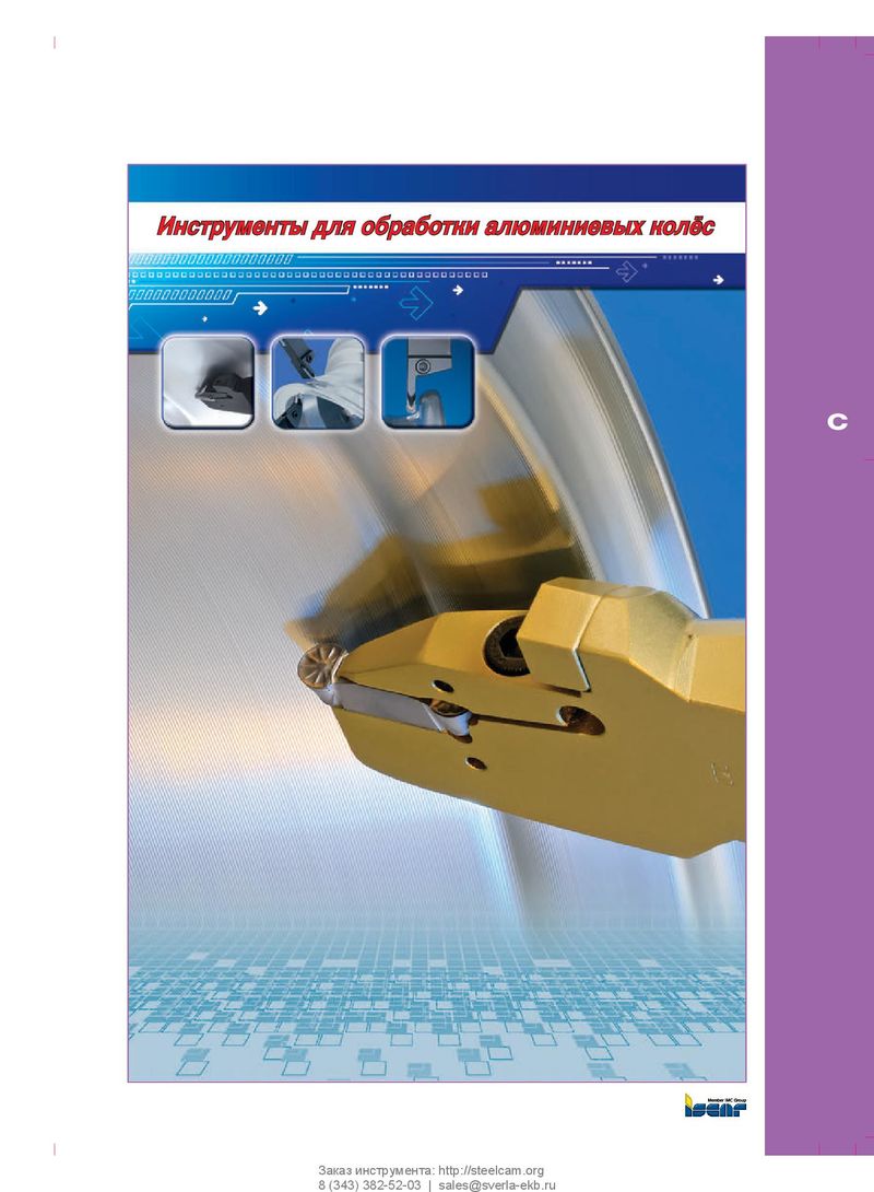 Каталог Iscar инструмент для обработки алюминиевых колёс
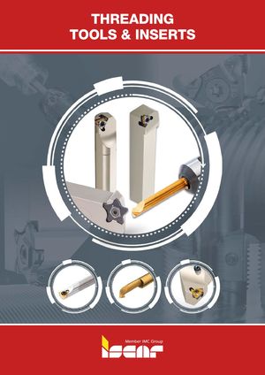 Каталог Iscar державки и пластины для нарезания резьбы 2022
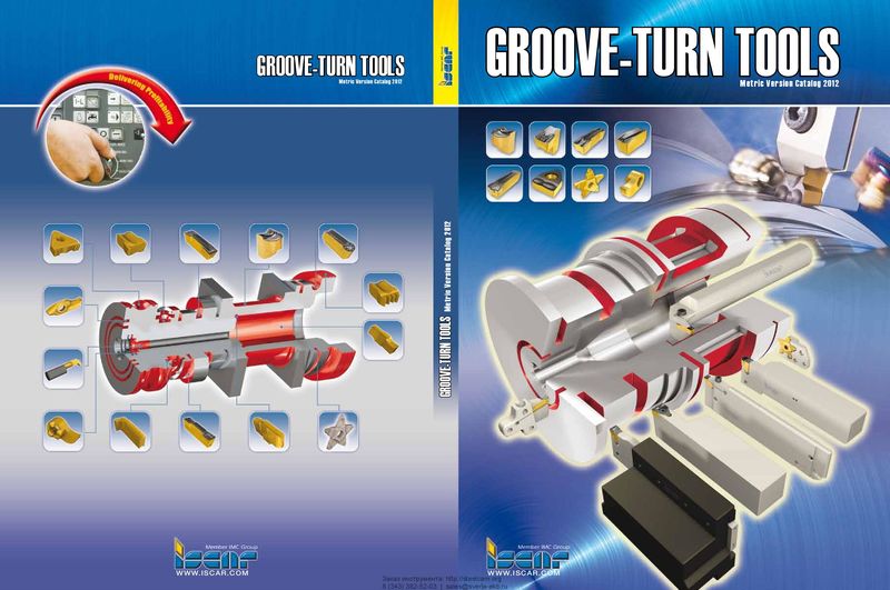 Каталог Iscar токарный инструмент для нарезания канавок
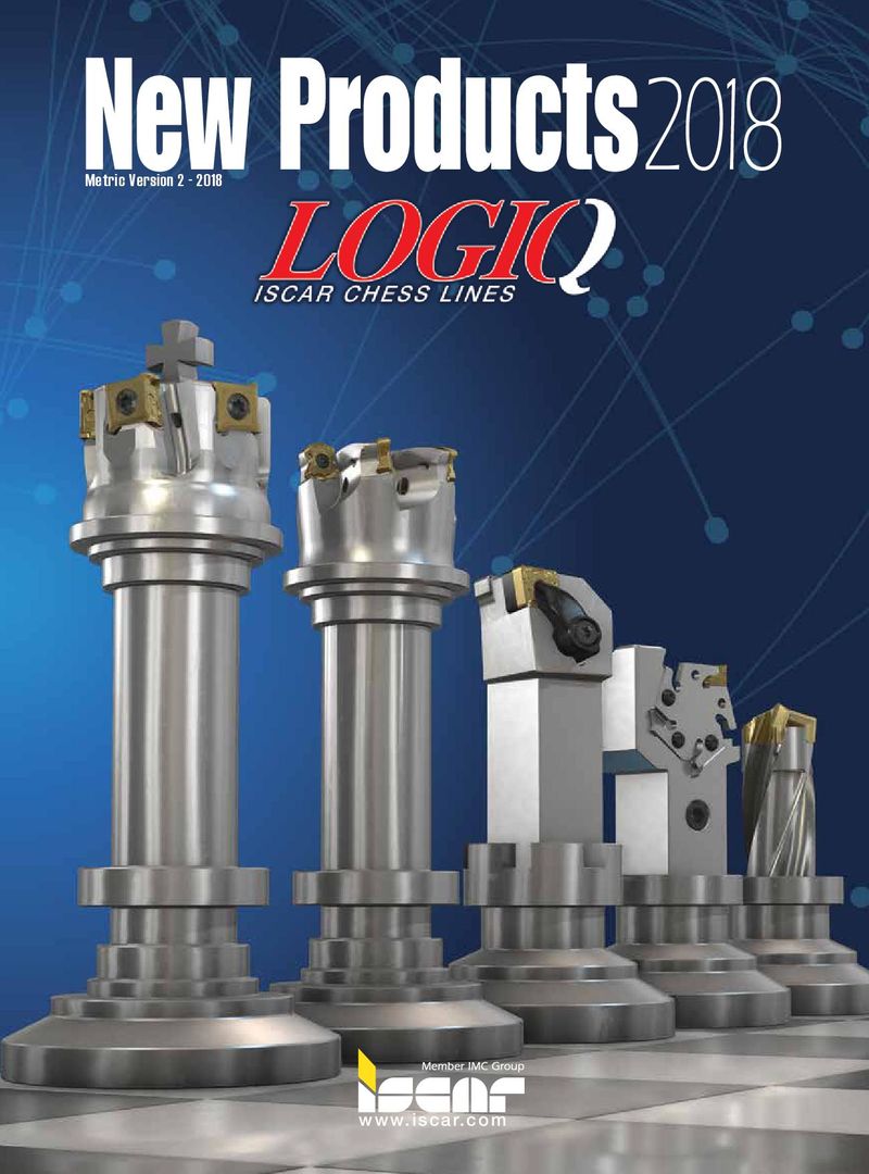 Каталог Iscar новые продукты 2018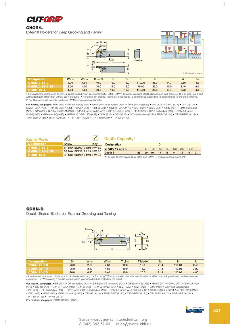
GHGR/L
External Holders for Deep Grooving and Parting
l2 Dmax
h h h4 A W l 1 f b Left-hand shown
| Designation | W min | W max | D max(2) | h | b | l1 | l2 | f | A | h4 |
| GHGR/L 16-3 | 3.00 | 4.00 | 40.0 | 16.0 | 16.0 | 110.00 | 36.0 | 14.7 | 2.50 | 4.0 |
| GHGR/L 16-3 ST (1) | 3.00 | 4.00 | 34.0 | 16.0 | 16.0 | 78.00 | 33.0 | 15.0 | 2.40 | 4.0 |
| GHGR 16-4 | 4.00 | 5.00 | 40.0 | 16.0 | 16.0 | 110.00 | 36.0 | 14.4 | 3.20 | 4.0 |
- For machining depth over 13 mm, a single-ended insert is required (GIM, GIMF, GIMY). Tmax for grooving depth depends on part diameter D. For grooving a part
with a diameter larger than Dmax, see next table. For using TIP inserts, toolholder seat needs to be modified according to insert profile to ensure clearance. (1) For Star and multi-spindle machines. (2) Maximum parting diameter For inserts, see pages: GIF (A34) GIF (full radius) (A34) GIF-E (W=4-6 full radius) (A30) GIF-E (W=4-6) (A29) GIG (A32) GIM-C (A77) GIM-J (A77) GIM-J-RA/LA (A78) GIM-UT (A79) GIM-UT-RA/LA (A80) GIM-W (A78) GIM-W-RA/LA (A79) GIMF (A27) GIMN (A28) GIMY (A27) GIMY (full radius) (A28) GIP (A33) GIP (flat top W<M) (A31) GIP (full radius W<M) (A31) GIP (full radius) (A33) GIP-E (A29) GIP-E (full radius) (A30) GIPA (full radius W=3-6) (A37) GIPA (W=3-6) (A36) GIPM-A46 / GIP-1250 (A38) GIPY (A36) GITM (A35) GITM (full radius) (A35) TIP-MT (A114) TIP-P-BSPT (A122) TIP-P-BSW (A121) TIP-P-ISO (A117) TIP-P-NPT (A128) TIP-P-UN (A119) TIP-WT (A112).
| SpareParts | Depth Capacity | |||||||||
| Designation | Screw Key | Designation | D | |||||||
| GHGR/L 16-3 | SR M6X16DIN912 12.9 HW 5.0 | GHGR/L 16-3/16-4 | — | 40 | 50 | 68 | 80 | 120 | 290 | 1000 — |
| GHGR/L 16-3 ST GHGR 16-4 | SR M6X16DIN912 12.9 HW 5.0 SR M6X16DIN912 12.9 HW 5.0 | Depth T | 23 | 20 | 19 | 17 | 16 | 14 | 12 | 11 9 |
* For over 13 mm depth: GIM, GIMF and GIMY, GPV (single ended insert) only.
CGHN-D
Double-Ended Blades for External Grooving and Turning
| D=2T Tblade | l1 | A B1 h1 W | ||||||
| Designation | B1 | Wmin | Wmax | T blmin | T blade | h1 | l1 | A |
| CGHN 26-3D | 26.0 | 2.80 | 4.00 | 10.0 | 15.0 | 21.4 | 110.00 | 2.40 |
| CGHN 26-4D | 26.0 | 3.50 | 4.50 | 10.0 | 15.0 | 21.4 | 110.00 | 3.20 |
| CGHN 26-5D | 26.0 | 4.40 | 6.40 | 10.0 | 20.0 | 21.4 | 110.00 | 4.00 |
- Use the yellow lines on blade for min. and max. overhang.
- For using TIP inserts, toolholder seat needs to be modified according to insert profile to ensure
clearance. When using a double-ended insert, grooving depth is limited by the insert. For inserts, see pages: GIF (A34) GIF (full radius) (A34) GIF-E (W=4-6 full radius) (A30) GIF-E (W=4-6) (A29) GIM-C (A77) GIM-J (A77) GIM-J-RA/LA (A78) GIM-UT (A79) GIM-UT-RA/LA (A80) GIM-W (A78) GIM-W-RA/LA (A79) GIMF (A27) GIMN (A28) GIMY (A27) GIMY (full radius) (A28)
- GIP (A33)
- GIP (full radius) (A33)
- GIP-E (A29)
- GIP-E (full radius) (A30)
- GIPA (full radius W=3-6) (A37)
- GIPA (W=3-6) (A36)
- GIPM-A46 / GIP-1250 (A38)
- GIPY (A36)
- GITM (A35)
- GITM (full radius) (A35)
- TIP-MT (A114)
- TIP-P-BSPT (A122)
- TIP-P-BSW (A121)
- TIP-P-ISO (A117)
- TIP-P-NPT (A128)
TIP-P-UN (A119) TIP-WT (A112). For holders, see pages: SGTBU/SGTBN (A88) .