Общий каталог Ingersoll 2011 - страница 1153
Навигация
 Общий каталог Ingersoll 2016 - 2017
 Общий каталог Ingersoll 2014
 Каталог Ingersoll инструмент для нарезания резьбы
 Общий каталог Ingersoll 2013 - 2014
 Каталог Ingersoll новинки 2021
- 0003 Table of Contents
- 0006 End Mills
- 0064 Long Edge
- 0104 0Deg Face Mills
- 0160 Face Mills
- 0202 Slotters
- 0218 Form Mills
- 0236 Profile Mills
- 0302 Milling Tech
- 0384 Solid Carbide
- 0448 Solid Carbide Tech
- 0474 Holemaking & Thread Milling
- 0666 Holemaking & Thread Milling Tech
- 0720 Innofit Top On Toolholders
- 0738 HSK Toolholders
- 0774 CAT Toolholders
- 0796 BT Toolholders
- 0816 Adaptions Accessories
- 0872 Turning Inserts
- 1024 Turning Holders
- 1144 Turning Tech
- 1174 Threading Inserts
- 1242 Threading Holders
- 1256 Threading Tech
- 1268 T-Clamp
- 1344 T-Clamp Tech
- 1376 T-CAP
- 1388 T-CAP Tech
- 1394 Product_Index
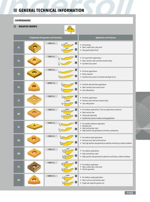
GENERAL TECHNICAL INFORMATION CHIPBREAKERS NEGATIVE INSERTS Chipbreaker Designation and Geometry Application and Features CNMG 43_ .0027” A • For finishing FC .0027” • Steel, carbon steel, alloy steel B • Very good surface finish CNMG 43_ A • For super finish applications FA • Steel, stainless steel and heat resistant alloys B • Excellent chip control CNMG 43_ A • For finish applications 15 EA • Exotic materials ° B • Excellent chip control in low feed and depth of cut 12 ,5° WNMG 33_ A • For finish and semi finish applications FG • Steel, stainless steel and cast iron B • Low cutting forces .0086” CNMG 43_ A 0° 14° • For finish applications SF .0059” • Stainless steel and.0086” heat resistant alloys B • Low cutting forces 0° 0° CNMG 43_ .0043” A • For medium applications / Pour les applications moyennes 0° • Steel and cast iron MC .0078” B • Strong rake geometry 0° • Excellent chip control on medium turning applications DNMG 43_ A • For slender workpiece application 13, • Vibration free 5° VF • Steel and stainless steel B • High positive rake geometry to minimize cutting force 13, 5° CNMG 43_ A • For medium light applications ML • Stainless steel, steel and aluminum B • Very high positive rake geometry to optimize machining in stable conditions CNMG 43_ .011” A • For medium applications 11° MP .011” • Steel and stainless steel B • High positive rake geometry to optimize machining in stable conditions 10° .009” CNMG 43_ A • For medium application PC .011” • Steel, carbon steel, alloy steel B • Positive geometry WNMG 43_ .0098” A • For medium rough applications 6° MT .011” • Steel, cast iron and stainless steel B • Tough rake angle for general use 4° 1155