Общий каталог Dijet 2018 - страница 37
Навигация
 Общий каталог Dijet 2012 на русском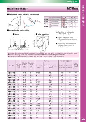
- Definition of corner radius for programming
| Corner | T | K rrεε | W | A aap | ||
| programming | Corner radius for programming | T | K r | W a | 1 p | |
| T | K ε | W | p A1 | |||
| radius 04 Type 04 Type | R1.5 (Recommended) | 0.29 0 | 1.5 | 2.7 0.8 0.8 | ||
| Remains: | R2 | 0.19 0.04 | ||||
| Over 04 Type | ||||||
| cut: 05 Type 05 Type | R2 (Recommended) | 0.35 0 | ||||
| K for | 0.25 0.12 1.6 | 3.6 1.25 1.2 | ||||
| r | 05 Type | R2.5 | ||||
| r ε | R2.5 (Recommended) | 0.44 0 | ||||
| ε | 06 Type 06 Type | 2.0 | 4.5 1.5 1.5 | |||
| T 06 Type | R3 | 0.34 0.1 | ||||
| R3 (Recommended) | 0.63 0 | |||||
| 08 Type 08 Type | R3.5 | 0.54 0.14 2.0 | 6.0 2.0 2.0 | |||
| W | 08 Type | R4 | 0.45 0.32 |
- W
Instructions for profile milling
- Calculation of tool passdia.
- Ramping
- Helical interpolation φdc = φDh − φDc
φDh
L φD Tool pass dia. Bore dia. Tool dia.
h L
- Depth of cut perone circle should not exceed max. depth of cut ap. Down cutting is recommended. ●Tool pass rotation should be
- counter-clockwise.
φdc φdc
- ●● In case of ramping and helical interpolation, apply 70% or less feed speed from standard cutting condition table.
- In case of drilling, apply 50% or less Z axis feed speed from standard cutting condition table.
- Long continous chips may come out in case of drilling, confirm the safe cutting conditions.
| Ramping | Helical in | terpolation | ||||||
| Cat. No. | Tool dia. φDc (mm) | Effective cutting dia. (mm) | Max.depth ofcut ap (mm) | Max. ramping angleθ° | Total cutting length L (m atmax.ap | m) Min. bore dia. Dh min (mm) | Max.bore dia. Dh max (mm) | Max. drilling depth (mm) |
| MSH-2016 | 16 | 10.5 | 0.8 | 2°30′ | 20.6 | 25 | 29 | 0.3 |
| MSH-2017 | 17 | 11.5 | 0.8 | 2° | 25.7 | 27 | 31 | 0.3 |
| MSH-2020 | 20 | 12.7 | 1.2 | 3° | 22.9 | 30 | 37 | 0.5 |
| MSH-3020 | 20 | 14.5 | 0.8 | 3° | 22.9 | 30 | 37 | 0.3 |
| MSH-2021 | 21 | 13.7 | 1.2 | 2°30′ | 27.5 | 32 | 39 | 0.5 |
| MSH-3021 | 21 | 15.5 | 0.8 | 2°30′ | 27.5 | 32 | 39 | 0.3 |
| MSH-2022 | 22 | 14.7 | 1.2 | 2° | 34.4 | 34 | 41 | 0.5 |
| MSH-3022 | 22 | 16.5 | 0.8 | 2° | 34.4 | 34 | 41 | 0.3 |
| MSH-2025 | 25 | 15.9 | 1.5 | 4° | 21.5 | 33 | 46 | 1 |
| MSH-3025 | 25 | 17.7 | 1.2 | 2° | 34.4 | 40 | 47 | 0.5 |
| MSH-2026 | 26 | 16.9 | 1.5 | 3°30′ | 24.5 | 35 | 48 | 1 |
| MSH-3026 | 26 | 18.7 | 1.2 | 1°54′ | 36.2 | 42 | 49 | 0.5 |
| MSH-2032 | 32 | 20 | 2 | 4° | 28.6 | 41 | 60 | 1.5 |
| MSH-3032 | 32 | 22.8 | 1.5 | 2°15′ | 38.1 | 47 | 60 | 1 |
| MSH-4032 | 32 | 24.7 | 1.2 | 1°18′ | 52.9 | 54 | 61 | 0.5 |
| MSH-2033 | 33 | 21 | 2 | 3°30′ | 32.7 | 43 | 62 | 1.5 |
| MSH-3033 | 33 | 23.8 | 1.5 | 2°6′ | 40.9 | 49 | 62 | 1 |
| MSH-2035 | 35 | 23 | 2 | 3° | 38.2 | 47 | 66 | 1.5 |
| MSH-3035 | 35 | 25.8 | 1.5 | 2° | 43 | 53 | 66 | 1 |
| MSH-5040 | 40 | 32.7 | 1.2 | 1° | 68.7 | 70 | 77 | 0.5 |
40 32.7 1.2 1° 68.7 70 77 0.5 B021B069
B069B069