Общий каталог Dijet 2018 - страница 230
Навигация
 Общий каталог Dijet 2012 на русском
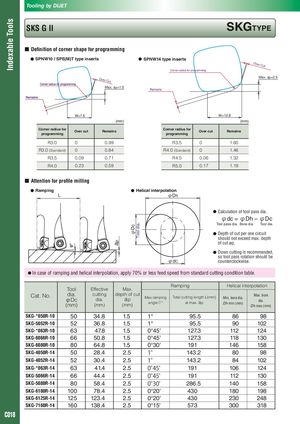
Indexable Tools ap φDc Tool dia. Tooling by DIJET SKS G II SKGTyPE ■ Definition of corner shape for programming ● SPnW10 / SPE(M)T type inserts ● SPnW14 type inserts Over Cut Corner radius for programming Over Cut Max. ap=2.5 Max. ap=1.5 Remains W=7.6 W=10.8 (mm) (mm) Corner radius for Over cut Remains Corner radius for Over cut Remains programming programming R3.0 0 0.99 R3.5 0 1.60 R3.0 (Standard) 0 0.84 R4.0 (Standard) 0 1.46 R3.5 0.09 0.71 R4.5 0.06 1.32 R4.0 0.23 0.59 R5.0 0.17 1.19 ■ Attention for profile milling ● Ramping ● Helical interpolation L φDh ● Calculation of tool pass dia. φdc = φDh – φDc Tool pass dia. Bore dia. Tool dia. ● Depth of cut per one circuit should not exceed max. depth of cut ap. ● Down cutting is recommended, so tool pass rotation should be φdC counterclockwise. ● In case of ramping and helical interpolation, apply 70% or less feed speed from standard cutting condition table. Ramping Helical interpolation Tool Effective Max. Cat. No. dia.φDc(mm) cuttingdia.(mm) depth of cutap Max.ramping(mm)angleθ°Total cutting length L(mm)at max. ap Min. bore dia.Dh min (mm)Max. boredia.Dh max (mm) SKG-*050R-10 50 34.8 1.5 1° 95.5 86 98 SKG-5052R-10 52 36.8 1.5 1° 95.5 90 102 SKG-*063R-10 63 47.8 1.5 0°45' 127.3 112 124 SKG-6066R-10 66 50.8 1.5 0°45' 127.3 118 130 SKG-6080R-10 80 64.8 1.5 0°30' 191 146 158 SKG-4050R-14 50 28.4 2.5 1° 143.2 80 98 SKG-4052R-14 52 30.4 2.5 1° 143.2 84 102 SKG-*063R-14 63 41.4 2.5 0°45' 191 106 124 SKG-5066R-14 66 44.4 2.5 0°45' 191 112 130 SKG-5080R-14 80 58.4 2.5 0°30' 286.5 140 158 SKG-6100R-14 100 78.4 2.5 0°20' 430 180 198 SKG-6125R-14 125 123.4 2.5 0°20' 430 230 248 SKG-7160R-14 160 138.4 2.5 0°15' 573 300 318 C018