Общий каталог Dijet 2018 - страница 141
Навигация
 Общий каталог Dijet 2012 на русском
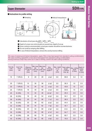
θ° (X) ap Tool dia. φDc Z Tooling by DIJET Super Diemaster SDHTYPE ■ Instructions for profile milling ● Ramping ● Helical Interpolation L φDh φDh φD1 φDc φdc Remains ● Calculation of tool pass dia.φdc = φDh − φDc Tool pass dia. Bore dia. Tool dia. ● Depth of cut per one circle should not exceed max. depth of cut ap. ● Down cutting is recommended, so tool pass rotation should be counterclockwise. ● Do not continue ramping after drilling. ● In case of helical interpolation, remove the core by traverse milling. ● In case of ramping and helical interpolation, apply 70% or less feed speed from standard cutting conditiontable. ● In case of drilling, apply50% or less Zaxis feed speed from standard cutting conditiontable. ● Long continous chips may come out in case of drilling, confirm the safe cutting conditions. Tool dia.φDc(mm)Insert dia.(mm)(R)Effective cutting dia. φD1 (mm) Min. bore dia. φDh min. (mm) Max.bore dia. φDh max. (mm)Max.rampingangleθ°Max. depthof cutap(mm)Total cuttinglengthL (mm)atmax. apMax. drilling depth Z (mm) Depth of holder face X (mm) 15 7 (R3.5) 8 20 28 3°00′ 3.5 66.8 0.4 1.0 16 7~(R3.5) 9 22 30 9°00′ 3.5 22.1 1.5 2.5 20 7 (R3.5) 13 30 38 5°30′ 3.5 36.3 1.5 2.5 22 7 (R3.5) 15 34 42 4°35′ 3.5 43.6 1.5 2.5 25 7 (R3.5) 18 40 48 3°40′ 3.5 54.6 1.5 2.5 25 10 (R5) 15 34 48 10°45′ 5.0 26.3 2.5 3.5 28 10 (R5) 18 40 54 8°20′ 5.0 34.1 2.5 3.5 30 10 (R5) 20 44 58 7°15′ 5.0 39.3 2.5 3.5 32 10 (R5) 22 48 62 6°25′ 5.0 44.4 2.5 3.5 32 12 (R6) 20 44 62 7°35′ 6.0 45.1 2.5 3.5 35 10 (R5) 25 54 68 5°30′ 5.0 51.9 2.5 3.5 35 12 (R6) 23 50 68 6°15′ 6.0 54.7 2.5 3.5 40 12 (R6) 28 60 78 4°55′ 6.0 69.7 2.5 3.5 42 10 (R5) 32 68 82 4°05′ 5.0 70.0 2.5 3.5 B125