Общий каталог Dijet 2018 - страница 116
Навигация
 Общий каталог Dijet 2012 на русском
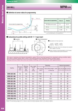
R θ° ap Tool dia.φDc Tooling by DIJET QM MILL MPMTYPE ■ Definition of corner radius for programming (mm) Over cut Corner radius for programming Over cut Remains R1 R1.0(Recommended) 0 0.17 R1.5 0.09 0.08 Remains R2.0 0.30 0 W=1.7 Note) In case of setting corner radius for programming to R2, recommend to use EOMT060220ZER or EOHW060220ZTR. ■ Instructions for profile milling with EO ※※ type insert ● Ramping ● Helical interpolation L φDh ●Calculation of tool pass dia. φdc = φDh −φDc Tool pass dia. Bore dia. Tool dia. ●Depth of cut per one circle should not exceed max. depth of cut ap. ● Down cutting is recommended, so tool pass rotation should becounterclockwise. φdc ●In case of ramping and helical interpolation, apply 70% or less feed speed from standard cutting condition table. ●In case of drilling, apply 50% or less Z axis feed speed from standard cutting condition table. ●Long continous chips may come out incase of drilling, confirm the correct cuttin gparameters. Ramping Helical interpolation Cat.No. Tool dia. EffectiveφDccutting(mm)dia.(mm)Max. depthof cutap(mm)Max.rampingTotal cutting length L (mm) Min. bore dia. Max. bore dia.angleθ°at max. apDh min (mm)Dh max (mm) MPM-2010-M6 10 6.6 0.3 2°18´ 7.5 15 18 MPM-2011-M6 11 7.6 0.3 1°54´ 9 17 20 MPM-3012-M6 12 8.5 0.3 1°36´ 10.7 19 22 MPM-3013-M6 13 9.5 0.3 1°24´ 12.3 21 24 MPM-4016-M8 16 12.5 0.4 1° 22.9 27 30 MPM-4017-M8 17 13.5 0.4 0°54´ 25.5 29 32 MPM-5020-M10 20 16.5 0.4 0°45´ 30.6 35 38 MPM-5021-M10 21 17.5 0.4 0°42´ 32.7 37 40 MPM-6025-M12 25 21.5 0.4 0°30´ 45.8 45 48 MPM-7030-M16 30 26.5 0.4 0°27´ 50.9 55 58 MPM-8032-M16 32 28.5 0.4 0°24´ 57.3 59 62 Note) The ramping angle 0.5° or less is recommended (please refer to the above table). B100