Общий каталог Widia 2017 - страница 507
Навигация
 Каталог Widia токарный инструмент 2017
 Каталог Widia трохоидальное фрезерование
 Каталог Widia техническое руководство по разверткам
 Каталог Widia фрезы со сменными пластинами 2016
 Каталог Widia достижения 2020
- Table of Contents
- Turning
- Turning • ISO Inserts
- Turning • Tools for External Turning and Internal Boring
- Turning • Tools for External Turning and Internal Boring
- Turning • Tools for Small Hole Boring
- com E1Turning • Grooving and Cut-Off
- Turning • Threading
- Indexable Milling
- Indexable Milling • Face Mills
- Indexable Milling • Chamfer Mills
- Indexable Milling • 90° Shoulder Mills
- Indexable Milling • Helical Mills
- Indexable Milling • Slotting Mills
- Indexable Milling • Copy Mills
- Solid End Milling
- Solid End Milling • High-Performance Solid Carbide End Mills
- Solid End Milling • General Purpose Solid Carbide End Mills
- Solid End Milling • High-Performance High-Speed Steel (HSS-E/PM)
- Solid End Milling • Burs
- Holemaking
- Holemaking • High-Performance Solid Carbide Drills
- Holemaking • Modular Drills
- Holemaking • Indexable Drills
- Holemaking • Modular Drills
- Holemaking • Indexable Drills
- Holemaking • Hole Finishing
- Tapping
- Tapping Portfolio
- Index by Order Number
- Index by Catalogue Number
- Global Contacts
- Informational Icons Guide
- Material Overview • DIN
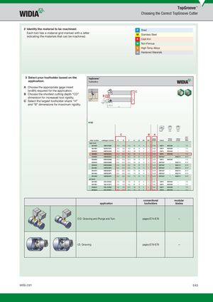
TopGroove™ Choosing the Correct TopGroove Cutter 2 Identify the material to be machined: P Steel Each tool has a material grid marked with a letterindicating the materials that can be machined. M Stainless Steel K Cast Iron N Non-Ferrous S High-Temp Alloys H Hardened Materials 3 Select your toolholder based on the TopGroove™ application: Toolholders A Choose the appropriate gage insert (width) required for the application.BChoose the shortest cutting depth “CD”dimension for increased tool rigidity. B CD H C C Select the largest toolholder shank “H” F B4 B 3° and “B” dimensions for maximum rigidity. L2 L1 n NS C B A hex/ gage clamp clamp Torx order number catalogue number H B F L1 L2 B4 CD insert clamp screw screw Plus right hand 3641682 NSR1010E2 10,0 10,0 14,0 70 19 9 4 N.2R CM74 MS1200 — T10 3641660 NSR1212F2 12,0 12,0 16,0 80 19 9 4 N.2R CM74 MS1200 — T10 3636542 NSR1616H2 16,0 16,0 20,0 100 19 9 4 N.2R CM74 MS1200 — T10 3638589 NSR2020K2 20,0 20,0 25,0 125 19 9 4 N.2R CM74 MS1200 — T10 3638588 NSR2020K3 20,0 20,0 25,0 125 32 13 5 N.3R CM72LP — MS2111 25 IP 3638590 NSR2525M2 25,0 25,0 32,0 150 19 9 4 N.2R CM74 MS1200 — T10 3636536 NSR2525M3 25,0 25,0 32,0 150 32 13 5 N.3R CM72LP — MS2111 25 IP 3636540 NSR2525M4 25,0 25,0 32,0 150 35 14 7 N.4R CM72LP — MS2111 25 IP 3641664 NSR3225P3 32,0 25,0 32,0 170 32 13 5 N.3R CM72LP — MS2111 25 IP 3641675 NSR3225P4 32,0 25,0 32,0 170 35 14 7 N.4R CM72LP — MS2111 25 IP 3641666 NSR3232P3 32,0 32,0 40,0 170 32 13 5 N.3R CM72LP — MS2111 25 IP 3641669 NSR3232P4 32,0 32,0 40,0 170 35 14 7 N.4R CM72LP — MS2111 25 IP left hand 3641683 NSL1010E2 10,0 10,0 14,0 70 19 9 4 N.2L CM75 MS1200 — T10 3641681 NSL1212F2 12,0 12,0 16,0 80 19 9 4 N.2L CM75 MS1200 — T10 3636545 NSL1616H2 16,0 16,0 20,0 100 19 9 4 N.2L CM75 MS1200 — T10 3639045 NSL2020K2 20,0 20,0 25,0 125 19 9 4 N.2L CM75 MS1200 — T10 conventional modular application toolholders blades O.D. Grooving and Plunge and Turn pages E74–E76 — I.D. Grooving pages E78–E79 — widia.com E43