Общий каталог Widia 2017 - страница 244
Навигация
 Каталог Widia токарный инструмент 2017
 Каталог Widia трохоидальное фрезерование
 Каталог Widia техническое руководство по разверткам
 Каталог Widia фрезы со сменными пластинами 2016
 Каталог Widia достижения 2020
- Table of Contents
- Turning
- Turning • ISO Inserts
- Turning • Tools for External Turning and Internal Boring
- Turning • Tools for External Turning and Internal Boring
- Turning • Tools for Small Hole Boring
- com E1Turning • Grooving and Cut-Off
- Turning • Threading
- Indexable Milling
- Indexable Milling • Face Mills
- Indexable Milling • Chamfer Mills
- Indexable Milling • 90° Shoulder Mills
- Indexable Milling • Helical Mills
- Indexable Milling • Slotting Mills
- Indexable Milling • Copy Mills
- Solid End Milling
- Solid End Milling • High-Performance Solid Carbide End Mills
- Solid End Milling • General Purpose Solid Carbide End Mills
- Solid End Milling • High-Performance High-Speed Steel (HSS-E/PM)
- Solid End Milling • Burs
- Holemaking
- Holemaking • High-Performance Solid Carbide Drills
- Holemaking • Modular Drills
- Holemaking • Indexable Drills
- Holemaking • Modular Drills
- Holemaking • Indexable Drills
- Holemaking • Hole Finishing
- Tapping
- Tapping Portfolio
- Index by Order Number
- Index by Catalogue Number
- Global Contacts
- Informational Icons Guide
- Material Overview • DIN
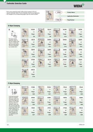
Toolholder Selection Guide Each unique clamping system offers product options to fill yourspecific toolholder needs. Find the illustration that fits your applicationDCKNProduct Name and navigate to the corresponding page to get the correct solution. Application Illustration Page: C8 Page Number D-Style Clamping D DCKN DCLN DCRN DCSN 75° 95° 75° 45° Page: Page: Page: Page: C8 C9 C10 C10 One-piece clamp assembly holder for DDJN DDNN DRGN DSDN use with negative styleinserts. An extremely 93° 63° 45° rigid clamping system. Page: Page: Page: Page: The tool is protected by a carbide shim. C11 C11 C12 C12 DSKN DSRN DSSN DTFN 75° 75° 45° 90° Page: Page: Page: Page: C13 C14 C15 C16 DTGN DVJN DVON DVVN 90° 93° 117,5° 72,5° Page: Page: Page: Page: C16 C17 C18 C18 DWLN 95° Page: C19 P-Style Clamping P PCBN PCKN PCLN PDJN 75° 75° 95° 93° Page: Page: Page: Page: C20 C21 C22 C23 Lever-type clamping system for negative PDNN PSBN PSDN PSKN indexable inserts with hole to DIN 4988 and 62,5° 75° 45° 75° positive round inserts Page: Page: Page: Page: more than 20mm in diameter. Inserts with C24 C25 C26 C26 one- and two-side chip control geometries have positive rakes from 6° PSSN PTFN PTGN PWLN to 18°. Advantages ofthis system are fast 45° 90° 90° 95° insert changes and Page: Page: Page: Page: no interference with chip flow. C27 C28 C29 C30 C4 widia.com