Каталог Widia достижения 2020 - страница 148
Навигация
 Каталог Widia инструмент для обработки отверстий 2017
 Каталог Widia токарный инструмент 2020
 Каталог Widia монолитный инструмент 2017
 Каталог Widia техническое руководство по разверткам
 Каталог Widia инструментальная оснастка
- Table of contents
- All-Star
- Indexable Milling
- VSM890™-12
- VXF™
- VXF-07
- VXF-09
- VXF-12
- VXF-16
- VXF Best practices
- Heavy Metal Extensions
- Solid ER Collets
- VSM
- VSM11
- VSM17
- Solid End Milling
- The VariMill Family
- 70NS
- 4U50 & 4U80
- 4U50
- 4U80
- 49N9
- D503
- General Purpose End Mills
- Holemaking
- TDMX
- Top Cut 4
- Turning
- WGC
- WK15CT
- Railway Tooling
- Bar Peeling
- Informational Icons Guide
- Customer Application Support (CAS)
- Material Overview • DIN
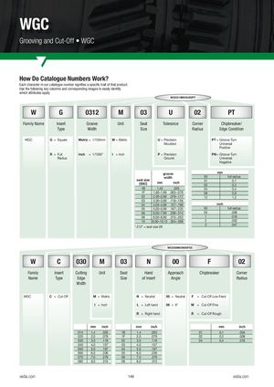
WGC Grooving and Cut-Off • WGC How Do Catalogue Numbers Work? Each character in our catalogue number signifies a specific trait of that product. Use the following key columns and corresponding images to easily identify which attributes apply. WG0312M03U02PT W G 0312 M 03 U 02 PT Family Name Insert Groove Unit Seat Tolerance Corner Chipbreaker/ Type Width Size Radius Edge Condition WGC G = Square Metric = 1/100mm M = Metric U = Precision PT = Groove-Turn Moulded Universal Positive R = Full Inch = 1/1000" I = Inch P = Precision PN = Groove-Turn Radius Ground Universal Negative groove mm width 00 full radius seat size(SSC) mm inch 0102 0,10,2 1B 1,40 .055 04 0,4 1F 1,60–1,99 .063–.078 08 0,8 02 2,00–2,99 .079–.117 12 1,2 03 3,00–3,99 .118–.156 04 4,00–4,99 .157–.196 inch 05 5,00–5,99 .197–.235 00 full radius 06 6,00–7,99 .236–.314 05 .008 08 8,00–8,99 .315–.353 1 .016 10 9,00–10,12 .354–.398 2 .032 *.312" = seat size 08 3 .047 WC030M03N00F02 W C 030 M 03 N 00 F 02 Family Insert Cutting Unit Seat Hand Approach Chipbreaker Corner Name Type Edge Size of Insert Angle Radius Width WGC C = Cut-Off M = Metric N = Neutral 00 = Neutral F = Cut-Off Low Feed I = Inch L = Left hand 06 = 6° M = Cut-Off Fine R = Right hand R = Cut-Off Rough mm inch mm inch mm inch 014 1,4 .055 1B 1,4 .055 01 0,1 .004 020 2,0 .079 1F 2,0 .079 02 0,2 .008 030 3,0 .118 02 3,0 .118 04 0,4 .016 040 4,0 .157 03 4,0 .157 050 5,0 .197 04 5,0 .197 060 6,0 .236 05 6,0 .236 070 7,0 .279 06 7,0 .279 080 8,0 .315 08 8,0 .315 widia.com 146 widia.com