Каталог Widia all star 2020 - страница 374
Навигация
 Каталог Widia техническое руководство по разверткам
 Каталог Widia достижения 2020
 Каталог Widia инструмент для обработки отверстий 2017
 Каталог Widia монолитный инструмент 2017
 Каталог Widia цельные концевые фрезы
- TABLE OF CONTENTS
- INDEXABLE MILLING
- 0º/90º SHOULDER MILLS
- 90° HIGH-SPEED CUTTING MILLS
- FACE MILLS
- HIGH-FEED MILLS
- COPY MILLS
- SOLID END MILLING
- HIGH-PERFORMANCE SOLID CARBIDE END MILLS
- GENERAL PURPOSE SOLID CARBIDE END MILLS
- HOLEMAKING
- SOLID CARBIDE DRILLS
- MODULAR DRILLS
- INDEXABLE DRILLS
- TAPPING
- TURNING
- HIGH-PERFORMANCE INSERTS
- GROOVING & CUT-OFF
- Informational Icons Guide
- Material Overview • DIN
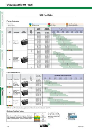
vvvjv vjvj vv vv vv jj TURNINGTAPPINGHOLEMAKINGSOLID END MILLINGINDEXABLE MILLING Grooving and Cut-Off • WGC WGC Feed Rates Plunge feed rates v first choice P Steel K Cast Iron S High-Temp Alloys j alternate choice M Stainless Steel N Non-Ferrous H Hardened Materials Corner StartingRadiusConditions Plunge Feed Rates inch/rev (mm/rev) Seat Chip Insert Size .0020 .0040 .0060 .0080 .0100 .0120 .0140 Control Description Geometry (SSC) in (mm) in (mm) (0,05) (0,10) (0,15) (0,20) (0,25) (0,30) (0,35) 1F .008 (0,2) .0024 (0,06) 2 .008 (0,2) .0031 (0,08) 3 .008 (0,2) .0035 (0,09).016 (0,4).0043 (0,11) 4 .016 (0,4) .0047 (0,12).031 (0,8).0059 (0,15) Positive rake-PTangle for lowercutting forces.5 .016 (0,4) .0059 (0,15).031 (0,8).0059 (0,16) .016 (0,4) .0059 (0,15) 6 .031 (0,8) .0071 (0,18) .047 (1,2) .0079 (0,20) 8 .031 (0,8) .0079 (0,20).047 (1,2).0087 (0,22) 10 .047 (1,2) .0094 (0,24) 1F .008 (0,2) .0024 (0,06) 2 .008 (0,2) .0031 (0,08) 3 .008 (0,2) .0035 (0,09).016 (0,4).0043 (0,11) Stable negative 4 .016 (0,4) .0047 (0,12).031 (0,8).0059 (0,15) cutting edge-PNallowing formore aggressive5 .016 (0,4) .0059 (0,15).031 (0,8).0059 (0,16) applications. .016 (0,4) .0059 (0,15) 6 .031 (0,8) .0071 (0,18) .047 (1,2) .0079 (0,20) 8 .031 (0,8) .0079 (0,20).047 (1,2).0087 (0,22) 10 .047 (1,2) .0094 (0,24) Cut-Off Feed Rates StartingConditions Cut-Off Feed Rates inch/rev (mm/rev) Seat Insert Size .0020 .0040 .0060 .0080 .0100 .0120 .0140 .0160 Geometry Description Geometry (SSC) in (mm) (0,05) (0,10) (0,15) (0,20) (0,25) (0,30) (0,35) (0,40) 1B .0024 (0,06) Positive 2 .0028 (0,07) -F geometryfor reduced 3 .0035 (0,09)4.0043 (0,11) cutting forces. 5 .0051 (0,13) 1B .0024 (0,06) 2 .0028 (0,07) Stable cutting 3 .0035 (0,09) edge for-Maggressive feedrates. Primarily4 .0043 (0,11)5.0055 (0,14) in cast iron. 6 .0063 (0,16) 8 .0067 (0,17) 2 .0039 (0,10) 3 .0055 (0,14) Most stable 4 .0063 (0,16) -R cutting edge 5 .0075 (0,19) for steel. 6 .0083 (0,21) 8 .0090 (0,23) NOTE: For cut-off inserts with a lead angle, maximum feed rate should be reduced by up to 40%. Maximum Feed Rate Values I.D. and Face Grooving Material Feed Group Factor For I.D. and face grooving Data above is for P and K material groups. Maximumfeed rates should be adjusted by multiplying max feed rateMvalues by following factors for shown material groups.N0.8applications, reduce feed1.2rate by 20%. S 0.8 H 0.5 E86 widia.com