Каталог Tungaloy глубокое сверление 1 - страница 60
Навигация

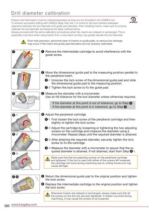
Drill diameter calibration Please note that inserts must be ordered separately as they are not included in the UNIDEX tool. To achieve successful drilling with UNIDEX deep hole drill, it is critical to set and maintain adequate clearance between the tool diameter and guide pad diameter. After installing inserts, make sure to properly calibrate the tool diameter by following the steps outlined below. Always proceed with the same calibration procedures when the inserts are indexed or exchanged. This is especially important when using inserts from a new batch as they may greatly deviate the tool diameter. Poor hole precision, abnormal wear of inserts or guide pads, or serious tool damage may occur if the insert and guide pad diameters are not properly calibrated. 1 1 Remove the intermediate cartridge to avoid interference with the guide screw. 2 2 Move the dimensional guide pad to the measuring position parallel to the peripheral insert. 2 -1 Unscrew the lock screw of the dimensional guide pad and slide the dimensional guide pad to the measuring position. 2 -2 Tighten the lock screw to fix the guide pad. 3 3 Measure the diameter with a micrometer. Use an h8 tolerance for the tool diameter unless otherwise required. If the diameter at this point is out of tolerance, go to Step 4 . If the diameter at this point is in tolerance, go to Step 5. 4 -1 4 Adjust the peripheral cartridge 4 -1 First loosen the lock screw of the peripheral cartridge and then slightly re-tighten the lock screw. 4 -2 Adjust the cartridge by loosening or tightening the two adjusting screws on the cartridge and measure the diameter using a 4 -2 micrometer. Repeat steps until the required diameter is attained. 4 -3 After attaining the required diameter, securely tighten the lock screw to fix the cartridge. 4 -4 Measure the diameter with a micrometer to assure that the re- quired diameter is attained. If not attained, start from Step 4 -1. 4 -3 Make sure that the two adjusting screws on the peripheral cartridge are tightened. If the tool is used with either of the screws left loosened, the cartridge will move during machining due to cutting forces and may cause damage. 5 6 5 Return the dimensional guide pad to the original position and tighten the lock screw. 6 Replace the intermediate cartridge to the original position and tighten the lock screw. Whenever inserts are indexed or exchanged, always make sure that all the screws on the drill are securely tightened. If chatter occurred during machining, it may cause the screws to be loosened. 060 www.tungaloy.com
 Брошюра Tungaloy новая продукция
 Каталог Tungaloy инструмент для автоматов швейцарского типа
 Каталог Tungaloy глубокое сверление 2
 Общий каталог Tungaloy 2020 - 2021
 Каталог Tungaloy зубофрезерование