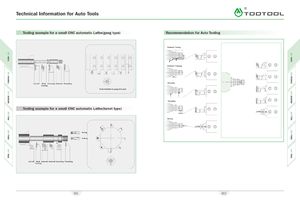
Каталог TooTool техническая информация 2 - страница 30
Навигация
 Каталог TooTool техническая информация 1
 Общий каталог TooTool
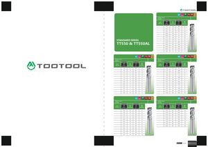 Каталог TooTool монолитные фрезы
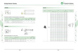
Circlip Groove Series A\ CTGVR/L Inserts 4 Size Coated X Shape Designation Configuration W ±0.025 La max r£ IC H d TTIM45 TTIS30 h ITT L t S 033 0.33 0.80 0.05 9.525 3.18 4.60430.431.200.059.5253.184.6 W 050 0.50 1.20 0.05 9.525 3.18 4.6 065 0.65 2.20 0.05 9.525 3.18 4.6 075 0.75 2.20 0.05 9.525 3.18 4.6 Perpendicular toolholder for external grooving, for 3 corner inserts 080 0.80 2.20 0.10 9.525 3.18 4.6 085 0.85 2.20 0.10 9.525 3.18 4.6 Spare parts Stock Dimensions(mm) 090 0.90 2.20 0.10 9.525 3.18 4.6 Designation Insert R L CWN-CWX H W h L i s Tmax Clamp Clamp Screw screw Wrench 095 0.95 2.20 0.10 9.525 3.18 4.61001.002.200.109.5253.184.6 CTGVR/L 1616-H16 0.33 - 3.00 16 16 16 100 16 20 3.2 T-15 110 1.10 2.20 0.10 9.525 3.18 4.6 2020-K16 0.33 - 3.00 20 20 20 125 20 27 3.2 TGF32R/L JTY16 JTS06 M4.0X10 115 1.15 2.20 0.10 9.525 3.18 4.6 HW30L 2525 -M16 0.33 - 3.00 25 25 25 150 20 32 3.2 120 1.20 2.20 0.10 9.525 3.18 4.6 Wj 125 1.25 2.20 0.10 9.525 3.18 4.6 42° ~ 130 1.30 2.20 0.10 9.525 3.18 4.6 \ 135 1.35 2.20 0.10 9.525 3.18 4.6 STGFR/L 140 1.40 2.20 0.10 9.525 3.18 4.6 -L - 4i1451.452.200.109.5253.184.6TGF32R/LICH 150 1.50 2.20 0.10 9.525 3.18 4.6 I 155 1.55 2.20 0.10 9.525 3.18 4.6 160 1.60 2.20 0.10 9.525 3.18 4.6 165 1.65 2.20 0.10 9.525 3.18 4.6 S 170 1.70 2.20 0.10 9.525 3.18 4.6 2° T H CWN-CWX 175 1.75 2.20 0.10 9.525 3.18 4.6 L 180 1.80 2.20 0.10 9.525 3.18 4.6 190 1.90 2.20 0.10 9.525 3.18 4.6 3 195 1.95 2.20 0.10 9.525 3.18 4.6 200 2.00 2.70 0.10 9.525 3.18 4.6 Internal grooving holder, for 3 corner inserts 220 2.20 2.70 0.10 9.525 3.18 4.6 Spare parts 225 2.25 2.70 0.10 9.525 3.18 4.6 Stock Dimensions(mm) Designation Insert 240 2.40 2.70 0.10 9.525 3.18 4.6 R L CWN-CWX Dmin d H L 2 S Tmax screw Wrench 250 2.50 2.70 0.10 9.525 3.18 4.6 270 2.70 2.70 0.15 9.525 3.18 4.6 S20Q-STGFR/L16 25 28 20 18 180 30 13.0 2.0 275 2.75 2.70 0.15 9.525 3.18 4.6 S25R-STGFR/L16 39 31 25 23 200 30 17.5 2.0 TGF32R/L M4.0xl0 T-15 300 3.00 3.20 0.15 9.525 3.18 4.6 S32S- STGFR/L16 44 38 32 30 250 45 19.0 2.0 415 416