Общий каталог Sumitomo 2019 - 2020 - страница 223
Навигация
 Каталог Sumitomo запасные части
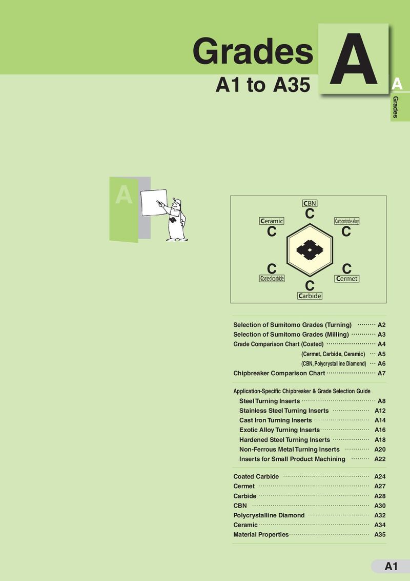 Каталог Sumitomo сплавы и режимы
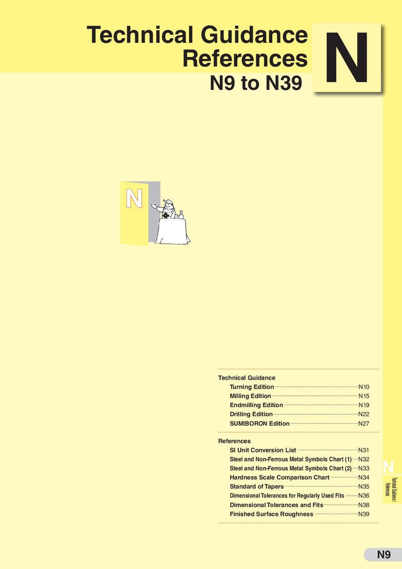 Техническая информация Sumitomo
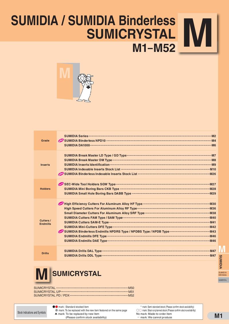 Каталог Sumitomo пластины с алмазными вставками Sumidia
 Каталог Sumitomo специальные торцевые фрезы
 Общий каталог Sumitomo 2018 - 2019
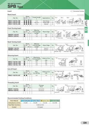
( 1. 0)0.11.0 0.1CW1.0 0.35±0.03 CW (1.2) 1.0 1.00.31.0 0.3355±0±.003.03 6.35 6.35 6.35 6.356.356.35 6.35 6.35 6.356.356.356.35 Lathes For Small SEC-PB Tool Holders SPB Type Insert ( Cemented Carbide) Blank Insert Dimensions (mm) Cat. No.PBVX 1102 R/L-NB StockBL130F1RLRL Overall lengthL Applications Fig Fig 1●●●●17.2Wide Range1 Fig 2SharpEdge Fig 3 3.0 35˚ PBVX 1102 R/L-SB ● ● ● ● (20.14) Sharp Edge 2 PBVX 1102 R/L-BB ● ● ● ● 17.2 Special 3 17 .2 (20.14) 17 .2 L 2.38 Figure shows right-hand (R) tool. Front Turning Insert Stock Effective Fig 1 Fig 2 Dimensions (mm) D Cat. No. BL130 F1 Cutting Edge Wiper Edge Fig 10˚ 5˚ R R L LengthPBVFW 1102 R/L●1.0Yes 1 2˚ 35˚ PBVFN 1102 R/L ● 1.0 No 2 Sharp Edge Sharp Edge 17.0 2.38 Figure shows right-hand (R) tool. Back Turning Insert Dimensions (mm) Stock Effective Fig 1 Fig 2 Cat. No. BL130 F1 Cutting Edge Wiper Edge Fig Maximum Depth of Cut Maximum Depth of Cut R R L Length 2.0 2.0PBVBW 1102 R/L●2˚5˚1.0Yes (2°)135˚ PBVBN 1102 R/L ● 1.0 No (5°) 2 Sharp Edge 50˚ Sharp Edge 50˚ 17.0 2.38 Figure shows right-hand (R) tool. Grooving Insert Dimensions (mm) Cat. No. StockBL130F1 MachiningGroove DepthWidth of Cut Fig Fig 1 Maximum Depth of Cut R R L CDX CW CDX 35˚ PBVG 1102 R/L-030 ● 0.5 0.3 1 PBVG 1102 R/L-050 ● 1.0 0.5 1 PBVG 1102 R/L-100 ● 2.0 1.0 1 17 .0 2.38Sharp Edge Figure shows right-hand (R) tool. Cut-off Insert Dimensions (mm) Cat. No. StockBL130F1RLRL Max.Cut-off Dia.Width of CutCW Fig 1 Right Hand (R)Fig 30˚Sharp2.5 Left Hand (L) PBVC 1102 R/L-50 ● ● 5.0 1.0 1 Edge 20˚ 17 .0 2.38 30˚ Threading Insert Dimensions (mm) StockCat. No.BL130F1RRL ProcessPitch Fig 1 Fig 2FigMaximum Depth of Cut3.0 2.5 PBVTF 1102 R/L ● 0.2 to 0.5 1 PBVTB 1102 R/L ● 0.2 to 0.5 2 60˚ 60˚ Max. RE 0.03 Max. RE 0.03 17.0 2.38 Figure shows right-hand (R) tool. Recommended Cutting Conditions Work Material P Free-Cutting Steel P Carbon Steel M Stainless Steel N Non-ferrous Metal Cutting Speed (vc) (m/min) 5 to 80 5 to 80 5 to 50 5 to 100 Feed Rate f (mm/rev) 0.003 to 0.05 Coolant Oil-based D9