Общий каталог Sumitomo 2019 - 2020 - страница 174
Навигация
 Каталог Sumitomo запасные части
 Каталог Sumitomo сплавы и режимы
 Техническая информация Sumitomo
 Каталог Sumitomo пластины с алмазными вставками Sumidia
 Каталог Sumitomo специальные торцевые фрезы
 Общий каталог Sumitomo 2018 - 2019
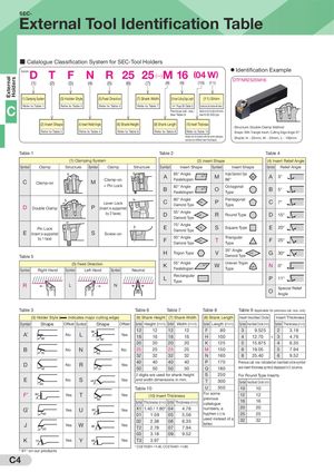
External Holders SEC- External Tool Identification Table ■ Catalogue Classification System for SEC-Tool Holders D Example: T F N R 25 25 (—)M 16 (04 W) ● Identification Example DTFNR2525M16 (1) (2) (3) (4) (5) (6) (7) (8) (9) (10) (11) (1) Clamping System (3) Holder Style (5) Feed Direction (7) Shank Width (9) Insert Cutting Edge Length (11) Shim C Refer to Table 1 Refer to Table 3 Refer to Table 5 Refer to Table 7 ☞ Page B3 (Table 5) Added only for holders with shims.Previous cat. nos.:Added only for holders with shimsSee Table 9meant for SEC-30/GD types. (2) Insert Shape (4) Insert Relief Angle (6) Shank Height (8) Shank Length (10) Insert Thickness · Structure: Double Clamp Method Refer to Table 2 Refer to Table 4 Refer to Table 6 Refer to Table 8 Refer to Table 10 · Shape: With Triangle Insert, Cutting Edge Angle 91° Added only for holders with the same cataloguenumbers but different insert thicknesses · Shank: H - 25mm, W - 25mm, L - 150mm Table 1 Table 2 Table 4 (1) Clamping System (2) Insert Shape (4) Insert Relief Angle Symbol Clamp Structure Symbol Clamp Structure Symbol Insert Shape Symbol Insert Shape Symbol Relief Angle C Clamp-on M Clamp-on A 85° AngleParallellogram 85˚ M Angle Diamond Type86° 86˚ A 3° + Pin Lock B 82° AngleParallellogram 82˚ O OctagonalType B 5° Lever LockDDouble ClampP(Insert is supportedC 80° AngleDiamond Type 80˚ P PentagonalType C 7° by 2 faces) D 55° Angle 55˚Diamond TypeR Round Type D 15° Pin LockE(Insert is supported S Screw-on E 75° AngleDiamond Type 75˚ S Square Type E 20° by 1 face) F 50° Angle 50˚Diamond TypeT TriangularType F 25° Table 5 H Trigon Type V 35° Angle 35˚Diamond TypeG 30° (5) Feed DirectionSymbolRight HandSymbolLeft HandSymbolNeutral K 55° AngleParallellogram 55˚ W Uneven TrigonType 80˚ N 0° L RectangularType P 11° R L N O Special ReliefAngle Table 3 Table 6 Table 7 Table 8 Table 9 Applicable for previous cat. nos. only (3) Holder Style ( indicates major cutting edge) (6) Shank Height (7) Shank Width (8) Shank Length Insert Inscribed Circle Insert Thickness Symbol Shape Offset Symbol Shape Offset Symbol Height (mm) Symbol Width (mm) Symbol Length (mm) Symbol Inscribed Circle (mm) Symbol Thickness (mm) A* 90˚ 95˚ 12 12 12 12 F 80 3 9.525 2 3.18NoLYes16161616H100412.70+34.7695˚ 20 20 20 20 K 125 5 15.875 4 6.35 B No N No 25 25 25 25 M 150 6 19.05 5 7.94 75˚ 63˚ 32 32 32 32 N 160 8 25.40 6 9.52 D 45˚ No R 75˚ 40 40 40 40Yes50505050 P 170 Previous cat. nos. indicated an inscribed circle symbolQ180and insert thickness symbol displayed in 2 columns. 2 digits are used for shank height S 250 For Round Type Inserts E No S 45˚60˚ Yes and width dimensions in mm. T 300 Symbol Inscribed Circle (mm) Table 10 U 350 10 10 F* 90˚ Yes T Yes (10) Insert Thickness For some 12 12 60˚ previousSymbol Thickness (mm) Symbol Thickness (mm)catalogue1616 G* Yes U 93˚ Yes X1 1.40 / 1.80* 04 4.76 numbers, a 20 20 90˚ 01 1.59 05 5.56 hyphen (-) is 25 25 J Yes W 60˚93˚ 02 2.38 06 6.35YesT22.78077.94 used instead of a 32 32letter. 03 3.18 09 9.52 K 75˚ Yes Y 85˚ Yes T3 3.97 * CCET03X1→1.40, CCET04X1→1.80 * 91° on our products C4