Общий каталог Sumitomo 2018 - 2019 - страница 294
Навигация
- Pages 3-6_CS6_EN_web
- A 1-20 insert selection EN_web
- B 1-14 grades_EN_web
- C01-17 inserts intro pages_EN_web
- C18-56 negative inserts_EN_web
- C57-86 positive inserts_EN_web
- D 1-46 tool holders_EN_web
- E 1-24 boring bars_EN_web
- F 1-48 grooving_thread tools_EN_web
- G 1-54 milling cutters_EN_web
- H 1-48 insert type endmills_EN_web
- J 1-24 new endmills_EN_web
- J 25-50 endmills_EN_web
- K 1-46 Multi-Drills_EN_web
- K 47-76 Multi-Drills_EN_web
- L 1-28 cbn_pcd grades_EN_web
- M 1-34 cbn_pcd inserts_EN_web
- M 35-56 SHM tools_EN_web
- N1-24 technical guidance_EN_web
- P 1-8 spare parts_neu_EN_web
- P 9-22 index_notes_EN_web

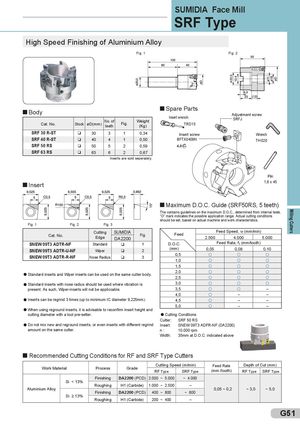
Milling Cutters SUMIDIA Face Mill SRF Type High Speed Finishing of Aluminium Alloy Fig. 1 Fig. 2 Body Spare PartsInsert wrenchCat. No.StockøD(mm)No. ofteethFig.Weight(Kg)TRD15Adjustment screwSRFJ SRF 30 R-ST q 30 3 1 0,34 Insert screw Wrench SRF 40 R-ST q 40 4 1 0,50 BFTX0409N TH 020 SRF 50 RS q 50 5 2 0,59 4,0 SRF 63 RS q 63 6 2 0,67 Inserts are sold seperately. Pin Insert 1,8 x 45 Maximum D.O.C. Guide (SRF50RS, 5 teeth) The contains guidelines on the maximum D.O.C., determined from internal tests. ”O” mark indicates the possible application range. Actual cutting conditions should be set, based on actual machine and work characteristics. Fig. 1 Fig. 2 Fig. 3 Cat. No. Cutting SUMIDIAEdgeDA2200Fig. Feed Feed Speed, vf (mm/min)2.5004.0005.000 SNEW 09T3 ADTR-NF Standard q 1 D.O.C. Feed Rate, f t (mm/tooth) SNEW 09T3 ADTR-U-NF Wiper q 2 (mm) 0,05 0,08 0,10 SNEW 09T3 ADTR-R-NF Nose Radius q 3 0,5 1,0 1,5 l Standard inserts and Wiper inserts can be used on the same cutter body. 2,0 2,5 l Standard inserts with nose radius should be used where vibration is 3,0 present. As such, Wiper-inserts will not be appliccable. 3,5 – 4,0 – – l Inserts can be regrind 3 times (up to minimum IC diameter 9,225mm). 4,5 – – 5,0 – – l When using reground inserts, it is advisable to reconfirm insert height and cutting diameter with a tool pre-setter. l Cutting Conditions Cutter: SRF 50 RS l Do not mix new and reground inserts, or even inserts with different regrind Insert: SNEW 09T3 ADFR-NF (DA2200) amount on the same cutter. n: 10.000 rpm Width: 35mm at D.O.C. indicated above Recommended Cutting Conditions for RF and SRF Type Cutters Work Material Process Grade Cutting Speed (m/min) Feed Rate Depth of Cut (mm)RF TypeSRF Type(mm /tooth)RF TypeSRF Type Finishing DA2200 (PCD) 2.000 ~ 5.000 ~ 4.000 Si < 13% Roughing H1 (Carbide) 1.000 ~ 2.500 – Aluminium Alloy 0,05 ~ 0,2 ~ 3,0 ~ 5,0 Finishing DA2200 (PCD) 400 ~ 800 ~ 800 Si ≥ 13% Roughing H1 (Carbide) 200 ~ 400 – G51
 Общий каталог Sumitomo 2012
 Каталог Sumitomo резьбонарезной инструмент
 Каталог Sumitomo пластины с режущей кромкой-моноалмаз Sumicristal
 Каталог Sumitomo инструмент для обработки канавок
 Общий каталог Sumitomo 2019 - 2020
 Каталог Sumitomo запасные части