Общий каталог Sumitomo 2018 - 2019 - страница 208
Навигация
 Общий каталог Sumitomo 2012
 Каталог Sumitomo резьбонарезной инструмент
 Каталог Sumitomo пластины с режущей кромкой-моноалмаз Sumicristal
 Каталог Sumitomo инструмент для обработки канавок
 Общий каталог Sumitomo 2019 - 2020
 Каталог Sumitomo запасные части
- Pages 3-6_CS6_EN_web
- A 1-20 insert selection EN_web
- B 1-14 grades_EN_web
- C01-17 inserts intro pages_EN_web
- C18-56 negative inserts_EN_web
- C57-86 positive inserts_EN_web
- D 1-46 tool holders_EN_web
- E 1-24 boring bars_EN_web
- F 1-48 grooving_thread tools_EN_web
- G 1-54 milling cutters_EN_web
- H 1-48 insert type endmills_EN_web
- J 1-24 new endmills_EN_web
- J 25-50 endmills_EN_web
- K 1-46 Multi-Drills_EN_web
- K 47-76 Multi-Drills_EN_web
- L 1-28 cbn_pcd grades_EN_web
- M 1-34 cbn_pcd inserts_EN_web
- M 35-56 SHM tools_EN_web
- N1-24 technical guidance_EN_web
- P 1-8 spare parts_neu_EN_web
- P 9-22 index_notes_EN_web
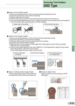
Parting-Off Grooving & Grooving Tool Holders GND Type Notes on how to Attach Inserts 1 Remove any foreign particles or oil from the insert seat before attaching the insert. 2 Ensure the seat location is clean and free of damage. 3 Slide the insert level over its seat. 4 Push the insert with its opposite end (the holder side) firmly against the insert stop end. 5 The recommended tightening torque is 5N.m. Tightening above the recommended torque may damage the insert or the holder which could cause injury and other accidents. 3 Attach insert on the seat flat. 4 Push insert fully into place. Torque: 5N.m Slide horizontally Insert stop end Notes on how to Apply Holders 1 Remove any foreign particles or oil from the tool post before attaching the holder. 2 Ensure the seat location is clean and free of damage. 3 Attach the holder so that the insert is perpendicular to the workpiece. 4 Set holder with shortest possible overhang. 5 When grooving or turning, adjust the center height of the cutting edge to as close ±0mm as possible. (Within ±0,1mm is recommended) 6 Incorrect center height adjustment may cause chattering. (In cut-off applications, adjust the center height of the cutting edge to a value from 0,0 to +0,2mm). A lower center height will result in larger nip at the center. 3 Attach at right angle 4 Set with short overhang 6 Center height adjustment to workpiece. in cut-off applTiocoal ptioostns Center height: 0 to ±0,2mm Overhang Work Piece Notes on Setting Coolant Supply Nozzle Maximum Depth of Cut Set the coolant supply nozzle so that coolant can Maximum depth of cut when pulling up with RG be supplied from the top of the upper clamp unit. chipbreaker Work Piece apmax Grooving Max. Depth of Cut Width (mm) (mm) w apmax 3,0 0,15 4,0 0,20 5,0 0,25 6,0 0,30 apmax 7,0 0,35 8,0 0,40 F13