Общий каталог Sumitomo 2018 - 2019 - страница 176
Навигация
- Pages 3-6_CS6_EN_web
- A 1-20 insert selection EN_web
- B 1-14 grades_EN_web
- C01-17 inserts intro pages_EN_web
- C18-56 negative inserts_EN_web
- C57-86 positive inserts_EN_web
- D 1-46 tool holders_EN_web
- E 1-24 boring bars_EN_web
- F 1-48 grooving_thread tools_EN_web
- G 1-54 milling cutters_EN_web
- H 1-48 insert type endmills_EN_web
- J 1-24 new endmills_EN_web
- J 25-50 endmills_EN_web
- K 1-46 Multi-Drills_EN_web
- K 47-76 Multi-Drills_EN_web
- L 1-28 cbn_pcd grades_EN_web
- M 1-34 cbn_pcd inserts_EN_web
- M 35-56 SHM tools_EN_web
- N1-24 technical guidance_EN_web
- P 1-8 spare parts_neu_EN_web
- P 9-22 index_notes_EN_web

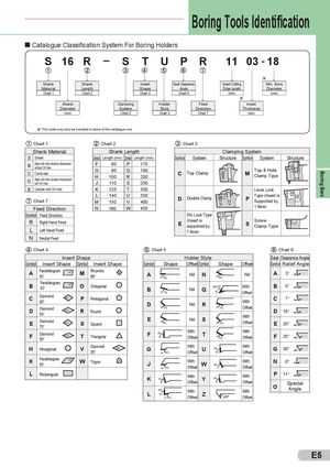
Boring Bars Boring Tools Identification Catalogue Classification System For Boring Holders S 16 R – S T U P R 11 03 - 18 h Shank Shank Insert Seat Clearance Insert Cutting Min. Bore Material Length Shape Angle Edge Length Diameter Chart 1 Chart 2 Chart 4 Chart 6 (mm) (mm) h Shank Clamping Holder Feed Insert Diameter System Style Direction Thickness (mm) Chart 3 Chart 5 Chart 7 (mm) h This code may only be included in some of the catalogue nos. Chart 1 Chart 2 Chart 3 Shank Material Shank Length Clamping System S Steel Symbol Length (mm) Symbol Length (mm) Symbol System Structure Symbol System Structure B Steel with Anti-vibration Mechanismwithout Oil HoleCCarbideDSteel with Anti-vibration Mechanismwith Oil HoleF80 P 170G90Q180H100R200J110S250 C Top Clamp M Top & HoleClamp Type E Carbide with Oil Hole K 125 T 300 Lever Lock Chart 7 L 140 U 350M150V400 D Double Clamp P Type (Insert isSupported by Feed Direction N 160 W 450 1 face) Symbol Feed Direction Pin Lock Type R Right Hand Feed E (Insert issupported by S ScrewClamp Type L Left Hand Feed 1 face) N Neutral Feed Chart 4 Chart 5 Chart 6 Insert Shape Holder Style Seat Clearance Angle Symbol Insert Shape Symbol Insert Shape Symbol Shape Offset Symbol Shape Offset Symbol Relief Angle A Parallellogram85° 85° M Rhombic86° 86¡ A 90¡ Nil N 63¡ Nil A 3° B Parallelogram82° 82¡ O Octagonal B 75¡ Nil Q With B 5°Offset C Diamond80° 80¡ P PentagonalDDiamond55°55¡RRoundEDiamond75°75¡SSquare D 45¡ Nil R 75¡ WithOffset C 7°D15°E60¡NilS45¡WithOffsetE20° F Diamond50° 50¡ T Triangular F 90¡ WithOffset T 60¡ WithOffset F 25° H Hexagonal V Diamond35° 35¡ G 90¡ WithOffsetU 93¡ WithOffset G 30° K Parallelogram55° 55¡ W Trigon 80¡ J 93¡ WithOffsetW 60¡ With N 0°Offset L Rectangular K 75¡ WithOffset Y 85¡95¡L95¡WithOffsetZ With P 11°OffsetWithOSpecialAngleOffset E5
 Общий каталог Sumitomo 2012
 Каталог Sumitomo резьбонарезной инструмент
 Каталог Sumitomo пластины с режущей кромкой-моноалмаз Sumicristal
 Каталог Sumitomo инструмент для обработки канавок
 Общий каталог Sumitomo 2019 - 2020
 Каталог Sumitomo запасные части