Общий каталог Sumitomo 2018 - 2019 - страница 134
Навигация
- Pages 3-6_CS6_EN_web
- A 1-20 insert selection EN_web
- B 1-14 grades_EN_web
- C01-17 inserts intro pages_EN_web
- C18-56 negative inserts_EN_web
- C57-86 positive inserts_EN_web
- D 1-46 tool holders_EN_web
- E 1-24 boring bars_EN_web
- F 1-48 grooving_thread tools_EN_web
- G 1-54 milling cutters_EN_web
- H 1-48 insert type endmills_EN_web
- J 1-24 new endmills_EN_web
- J 25-50 endmills_EN_web
- K 1-46 Multi-Drills_EN_web
- K 47-76 Multi-Drills_EN_web
- L 1-28 cbn_pcd grades_EN_web
- M 1-34 cbn_pcd inserts_EN_web
- M 35-56 SHM tools_EN_web
- N1-24 technical guidance_EN_web
- P 1-8 spare parts_neu_EN_web
- P 9-22 index_notes_EN_web

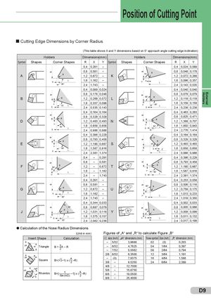
BBB sssssYssY YYY s YsYssYssYsY Y Y Holders External Position of Cutting Point Cutting Edge Dimensions by Corner Radius (This table shows X and Y dimensions based on 0° approach angle cutting edge inclination) Holders Dimensions(mm) Holders Dimensions(mm) Symbol Shapes Corner Shapes R X Y Symbol Shapes Corner Shapes R X Y 0,4 0,291 – 0,4 0,024 0,089 A 0,8 0,581 –R1,20,872–K 75° R 0,8 0,048 0,1781,20,0720,268 X L 1,6 1,162 –90°2,41,743– X 1,6 0,096 0,357L2,40,1430,535 0,4 0,089 0,024 0,4 0,040 0,040 0,8 0,178 0,048 0,8 0,079 0,079 B RR 1,2 0,268 0,072 L 95° R 1,2 0,119 0,119 1,6 0,357 0,096X75°L2,40,5350,143 95° L 1,6 0,159 0,159X2,40,2380,238 0,4 0,164 0,164 0,4 0,463 0,263 R 0,8 0,329 0,329D1,20,4930,493N 0,8 0,925 0,471R1,21,3880,707 X 45° L 1,6 0,658 0,6582,40,9860,986 X 63° L 1,6 1,850 0,9432,42,7761,414 0,4 0,396 0,229 0,4 0,164 0,164 0,8 0,793 0,458R R 0,8 0,329 0,329R E 1,2 1,190 0,687 S 45° 1,2 0,493 0,493 60°X L 1,6 1,587 0,9162,42,3811,374 X 1,6 0,658 0,658L2,40,9860,986 0,4 – 0,291 0,4 0,396 0,229 0,8 – 0,581 X 0,8 0,793 0,458 F R90° 1,2 – 0,872 T R 1,2 1,190 0,687 L 1,6 – 1,1622,4–1,743 X 60° L 1,6 1,587 0,9162,42,3811,374 0,4 0,291 – 0,4 0,253 0,058 G 0,8 0,581 –R1,20,872–U 95° R 0,8 0,506 0,1161,20,7590,175 X L 1,6 1,162 –90°2,41,743– 1,6 1,013 0,233XL2,41,5190,350 0,4 0,344 0,033 0,4 0,002 0,033 55° 0,8 0,687 0,079 0,8 0,005 0,066 J R 1,2 1,031 0,118 Y 85° R 1,2 0,008 0,099 L 1,6 1,375 0,157X X L 1,6 0,011 0,132 93° 2,4 2,062 0,236 2,4 0,017 0,198 Calculation of the Nose Radius Dimensions (Unit in mm) Figures of „A“ and „R“ to calculate Figure „B“ Insert Shape Calculation I.C. size (inch) „øA“ dimensions (mm) Nose symbol Size (inch) „R“ dimension (mm) R – 5/32 3,9688 02 (0) 0,203 ØA Triangle B = –32 A – R – 6/32 4,7625 04 1/64 0,397–7/325,5562082/640,794 R 2/8 8/32 6,3500 12 3/64 1,191 ØA Square B=( 2–1) x (–A2 –R) – (0) 7,9375 16 4/64 1,5883/8–9,5250246/642,389 4/8 – 12,7000 RØA Rhombic B={ –S–in––1(q–/–2–) –1} x ( –A2 –R) 5/8 – 15,87506/8–19,0500 8/8 – 25,4000 D9
 Общий каталог Sumitomo 2012
 Каталог Sumitomo резьбонарезной инструмент
 Каталог Sumitomo пластины с режущей кромкой-моноалмаз Sumicristal
 Каталог Sumitomo инструмент для обработки канавок
 Общий каталог Sumitomo 2019 - 2020
 Каталог Sumitomo запасные части