Общий каталог Mitsubishi 2020 - 2021 - страница 723
Навигация
 Каталог Mitsubishi Materials запасные части
 Каталог Mitsubishi Materials резьбонарезной инструмент
 Каталог Mitsubishi Materials СНП с CBN и PCD для токарной обработки
 Каталог Mitsubishi Materials сверлильные инструменты
 Каталог Mitsubishi Materials расточной инструмент
 Каталог Mitsubishi Materials пластины для точения
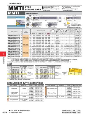
THREADING Stock WFWFLead Angle WF WFWF PDY THREADING MMTI TYPEBORING BARS a Minimum cutting diameter .500".a Various insert types.a Precision class insert for precisethread forms.a Available with a pressed breakerfor chip control.a Able to change lead angle byreplacing the shim. MMTI Internal threading GAMF15° Fig.1 (Screw-on type) Fig.2 (Screw-on type) LDREDDMINAGAMF15°Fig.3 (Clamp-on type)LF HDCONFig.4 (Clamp-on type)LDRED LFDetails of position A Refer to the insert standards PDX for dimensions PDX and PDY. DMIN LDRED LF LDRED LF LFRight hand tool holder only. Order Number InsertNumber Dimensions (inch) * * z x Fig. R DCON LF LDRED WF H DMIN Clamp Bridge Clamp Screw Stop Ring Shim Screw Shim Wrench MMTIR102-0.50-1.5-C a 1.5° .625 5.000 1.000 .340 .586 .500 – TS25 – – – zTKY08F 1 MMTIR102-0.50-2.5-C a MMT11IR 2.5° .625 5.000 1.000 .340 .586 .500 – TS25 – – – zTKY08F 1 MMTIR102-0.60-1.5-C a ooooo 1.5° .625 6.000 1.250 .380 .586 .600 – TS25 – – – zTKY08F 1 MMTIR102-0.60-2.5-C a 2.5° .625 6.000 1.250 .380 .586 .600 – TS25 – – – zTKY08F 1 MMTIR103-0.75-1.5-C a 1.5° .625 6.000 1.500 .480 .586 .750 – CS350860T – – – zTKY15F 2 MMTIR103-0.75-2.5-CMMTIR123-0.90-1.5-CMMTIR163-1.15-1.5-CaaMMT16IRooooo2.5°1.5°.6256.000 1.500 .480.7507.000 1.500 .510.586.750–CS350860T.711.900SETK51SETS51–CR4a1.5°1.000 10.000 2.500.660.937 1.150SETK51SETS51CR4––zTKY15F2HFC03006CTI32TP15zTKY15FxHKY20R3HFC03006CTI32TP15zTKY15FxHKY20R3 MMTIR203-1.45-1.5-C a 1.5° 1.250 10.000 2.000 .810 1.187 1.450 SETK51 SETS51 CR4 HFC03006 CTI32TP15 zTKY15FxHKY20R4 MMTIR124-0.95-1.5-C a 1.5° .750 7.000 2.000 .610 .711 .950 – TS43 – – – zTKY15F 2 G MMTIR124-0.95-2.5-CMMTIR164-1.20-1.5-CaaMMT22IRooooo 2.5°1.5° .7501.0007.000 2.000 .6108.000 1.500 .700.711.950–.937 1.200SETK61TS43SETS61MMTIR204-1.50-1.5-Ca1.5°1.250 10.000 2.000.860 1.187 1.500SETK61SETS61–––zTKY15F2CR5HFC04008CTI43TP15zTKY20FxHKY25R4CR5HFC04008CTI43TP15zTKY20FxHKY25R4 MMTIR244-1.75-1.5-C a 1.5° 1.500 12.000 2.500 .980 1.437 1.750 SETK61 SETS61 CR5 HFC04008 CTI43TP15 zTKY20FxHKY25R4 Note 1) Select and use an alternate shim from list below (sold separately), dependant on the lead angle. • The screw-on type has no shim. The holder has an in-built lead angle. Please select a holder with the appropriate lead angle. • The minimum cutting diameter (DMIN) indicates the prepared hole diameter, not the nominal thread diameter. * Clamp Torgue (lbf-in) : TS25=8.9, CS350860T=31, SETS51=31, TS43=31, SETS61=44, HFC03006=13, HFC04008=19 SHIM Lead Angle(%°)Order Number Stock Inclination AngleR('°)ApplicableHolder Lead Angle(%°)Order Number Stock Inclination AngleR('°)ApplicableHolder –1.5° CTI32TN15 a –3° –1.5° CTI43TN15 a –3°–0.5°CTI32TN05a–2°–0.5°CTI43TN05a–2° Insert 0.5° CTI32TP05 a –1° MMTIR1.5°CTI32TP15a0°oo3-ooo0.5° CTI43TP05 a1.5°CTI43TP15a–1°0° MMTIRoo4-ooo InclinationAngle('°)Shim 2.5° CTI32TP25 a 1° -oo-C 2.5° CTI43TP25 a 1° -oo-C 3.5° CTI32TP35 a 2° 3.5° CTI43TP35 a 2° 4.5° CTI32TP45 a 3° 4.5° CTI43TP45 a 3° Standard shim delivered with the holder. RECOMMENDED CUTTING CONDITIONS Work Material Hardness Grade Cutting Speed (SFM) Work Material Hardness Grade Cutting Speed (SFM) P VP10MF 490 (230 ─ 755) S VP10MF 150 (50 ─ 230) Mild Steel < 180HB VP15TF 330 (195 ─ 460) Heat-Resistant Alloy ─VP20RT260 (195 ─ 330)VP15TFVP20RT100 (65 ─ 130) Carbon SteelAlloy Steel VP10MF 460 (260 ─ 655)180 ─ 280HBVP15TF330 (195 ─ 460)VP20RT260 (195 ─ 330) VP10MF 195 (130 ─ 260)Titanium Alloy─VP15TFVP20RT150 (80 ─ 210) M Stainless Steel < 200HB VP15TFVP20RT 260 (130 ─ 395) H Heat-Treated Alloy 45 ─ 55HRC VP10MFVP15TF 165 (100 ─ 230)130 (65 ─ 195) K Gray Cast Iron Tensile Strength VP10MF< 350MPaVP15TF 460 (260 ─ 655)295 (195 ─ 395) a : USA Stock s : Stocked in Japan HOW TO SELECT A SHIM G012 G026 <5 inserts in one case> MMT SERIES ORDER NUMBER G020