Общий каталог Mitsubishi 2020 - 2021 - страница 714
Навигация
 Каталог Mitsubishi Materials запасные части
 Каталог Mitsubishi Materials резьбонарезной инструмент
 Каталог Mitsubishi Materials СНП с CBN и PCD для токарной обработки
 Каталог Mitsubishi Materials сверлильные инструменты
 Каталог Mitsubishi Materials расточной инструмент
 Каталог Mitsubishi Materials пластины для точения
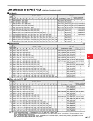
THREADING MMT STANDARD OF DEPTH OF CUT INTERNAL (RADIAL INFEED) yISO Metric (mm) Pitch(mm)TotalCuttingDepth123 4 5 Number of Passes6789 10 11 12 13 14 Insert TypeG-class ground insertsM-class inserts with3-D chip breakers 0.5 0.29 0.09 0.07 0.07 0.06 MMT11IR050ISO MMT16IR050ISO – – 0.75 0.43 0.15 0.13 0.09 0.06 MMT11IR075ISO MMT16IR075ISO – – 1.0 0.58 0.17 0.15 0.11 0.09 0.06 MMT11IR100ISO MMT16IR100ISO MMT11IR100ISO-S MMT16IR100ISO-S 1.25 0.72 0.18 0.16 0.12 0.11 0.09 0.06 MMT11IR125ISO MMT16IR125ISO MMT11IR125ISO-S MMT16IR125ISO-S 1.5 0.87 0.21 0.20 0.16 0.13 0.11 0.06 MMT11IR150ISO MMT16IR150ISO MMT11IR150ISO-S MMT16IR150ISO-S 1.75 1.01 0.21 0.20 0.15 0.12 0.10 0.09 0.08 0.06 MMT11IR175ISO MMT16IR175ISO – MMT16IR175ISO-S 2.0 1.15 0.24 0.22 0.18 0.14 0.12 0.10 0.09 0.06 MMT11IR200ISO MMT16IR200ISO – MMT16IR200ISO-S 2.5 1.44 0.25 0.24 0.21 0.15 0.13 0.12 0.10 0.09 0.09 0.06 – MMT16IR250ISO – MMT16IR250ISO-S 3.0 1.73 0.26 0.25 0.22 0.17 0.14 0.13 0.12 0.11 0.10 0.09 0.08 0.06 – MMT16IR300ISO – MMT16IR300ISO-S 3.5 2.02 0.32 0.30 0.23 0.19 0.17 0.15 0.14 0.13 0.12 0.11 0.10 0.06 – MMT22IR350ISO – – 4.0 2.31 0.33 0.31 0.24 0.22 0.18 0.15 0.14 0.13 0.12 0.12 0.11 0.10 0.10 0.06 – MMT22IR400ISO – – 4.5 2.60 0.36 0.33 0.28 0.24 0.21 0.19 0.16 0.15 0.14 0.13 0.12 0.12 0.11 0.06 – MMT22IR450ISO – – 5.0 2.89 0.41 0.38 0.32 0.27 0.24 0.21 0.18 0.16 0.15 0.14 0.13 0.12 0.12 0.06 – MMT22IR500ISO – – yAmerican UN (inch) Pitch Total Number of Passes Insert Type (thread/ Cuttinginch)Depth123 4 5 6 7 8 9 10 11 12 13 14 G-class ground inserts M-class inserts with3-D chip breakers 32 .018 .006 .006 .004 .002 MMT11IR320UN MMT16IR320UN – 28 .020 .006 .005 .004 .003 .002 MMT11IR280UN MMT16IR280UN – 24 .024 .007 .006 .005 .004 .002 MMT11IR240UN MMT16IR240UN – 20 .029 .007 .006 .005 .005 .004 .002 MMT11IR200UN MMT16IR200UN – G 18 .032 .008 .007 .006 .005 .004 .002 MMT11IR180UN MMT16IR180UN – 16 .036 .008 .007 .006 .005 .004 .004 .002 MMT11IR160UN MMT16IR160UN MMT16IR160UN-S 14 .041 .008 .007 .006 .005 .005 .004 .004 .002 MMT11IR140UN MMT16IR140UN MMT16IR140UN-S 13 .044 .009 .007 .006 .006 .005 .005 .004 .002 – MMT16IR130UN – 12 .048 .009 .009 .007 .006 .005 .005 .005 .002 – MMT16IR120UN MMT16IR120UN-S 11 .052 .009 .009 .008 .006 .005 .005 .004 .004 .002 – MMT16IR110UN – 10 .058 .010 .009 .008 .006 .005 .005 .005 .004 .004 .002 – MMT16IR100UN – 9 .064 .012 .009 .008 .007 .006 .006 .005 .005 .004 .002 – MMT16IR090UN – 8 .072 .012 .010 .008 .007 .006 .006 .006 .005 .005 .005 .002 – MMT16IR080UN – 7 .082 .014 .012 .009 .008 .007 .007 .006 .006 .006 .005 .002 – MMT22IR070UN – 6 .096 .016 .013 .010 .009 .007 .007 .006 .006 .006 .005 .005 .004 .002 – MMT22IR060UN – 5 .115 .016 .014 .012 .010 .009 .008 .008 .007 .007 .006 .006 .005 .005 .002 – MMT22IR050UN – yWhitworth for BSW, BSP (inch) Pitch Total Number of Passes Insert Type (thread/ Cuttinginch)Depth123 4 5 6 7 8 9 10 11 12 13 14 G-class ground inserts M-class inserts with3-D chip breakers 28 .023 .007 .006 .004 .004 .002 – MMT16IR280W – 26 .025 .007 .006 .005 .005 .002 – MMT16IR260W – 20 .032 .008 .007 .006 .005 .004 .002 – MMT16IR200W – 19 .034 .008 .007 .006 .006 .005 .002 MMT11IR190W MMT16IR190W MMT16IR190W-S 18 .035 .010 .007 .006 .005 .005 .002 – MMT16IR180W – 16 .040 .008 .007 .006 .005 .004 .004 .004 .002 – MMT16IR160W – 14 .046 .009 .008 .007 .006 .005 .005 .004 .002 MMT11IR140W MMT16IR140W MMT16IR140W-S 12 .054 .011 .010 .008 .006 .006 .006 .005 .002 – MMT16IR120W MMT16IR120W-S 11 .058 .011 .009 .008 .007 .006 .006 .005 .004 .002 – MMT16IR110W – 10 .064 .011 .010 .008 .007 .006 .006 .005 .005 .004 .002 – MMT16IR100W – 9 .071 .011 .010 .008 .007 .006 .006 .006 .005 .005 .005 .002 – MMT16IR090W – 8 .080 .012 .011 .009 .007 .007 .006 .006 .006 .005 .005 .004 .002 – MMT16IR080W – 7 .091 .013 .013 .010 .009 .008 .007 .007 .006 .006 .006 .004 .002 – MMT22IR070W – 6 .107 .014 .013 .011 .009 .008 .008 .007 .007 .006 .006 .006 .005 .005 .002 – MMT22IR060W – 5 .128 .017 .016 .014 .011 .010 .009 .009 .008 .007 .007 .007 .006 .005 .002 – MMT22IR050W – Note 1) · Set the finishing allowance on a diameter at approx. .004 inch when using a full form insert. · Please note the cutting depth and the number of passes when a nose radius of a partial or semi-full form insert or of an internal threading insert is small to prevent damage to the insert nose. · Please set the cutting depth sufficiently deep enough on materials such as hardened steel or austenitic stainless steel to help prevent premature wear and chipping caused by the outer layer of the material. G017