Общий каталог Mitsubishi 2020 - 2021 - страница 649
Навигация
 Каталог Mitsubishi Materials запасные части
 Каталог Mitsubishi Materials резьбонарезной инструмент
 Каталог Mitsubishi Materials СНП с CBN и PCD для токарной обработки
 Каталог Mitsubishi Materials сверлильные инструменты
 Каталог Mitsubishi Materials расточной инструмент
 Каталог Mitsubishi Materials пластины для точения
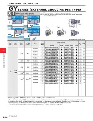
GROOVING / CUTTING OFF HF HF b2WF CDX DCON CUTDIA CUTDIA GROOVING / CUTTING OFF GYSERIES (EXTERNAL GROOVING PSC TYPE) 8-1 90° type holder (Inch) Note 1) For modular blades and holders, please order separately.Note 2) Please use right hand modular blade for right hand holder and left hand modular Insert GY2Mooooooooo--G GSM Insert GY2Gooooooooo-MF blade for left hand holder. Insert GY22M G ooooooooo--G GUL Insert GY2Mooooooooo-MS Insert GY11M G ooooooooo--G GFMGS Insert GY2Mooooooooo-MM CZC Fig. 1 Fig. 2 CW LHLF Insert GY2Mooooooooo-BM Insert GY2Mooooooooo--G GSM Insert GY22M G ooooooooo--G GUL Insert GY2MoooooR/Loo-GM Right hand tool holder shown. Seat CW CDX CUTDIASize(inch)(inch)(inch)TypeHand(R/L) Order Number Fig. CZCHolderStockModular BladeStock F Modular R C3-GYHRCX90-M20L a GYM20LA-D06LC3-GYHLCX90-M20RaGYM20RA-D06aa11C3.236.472ModularRC4-GYHRD90-M25LLC4-GYHLD90-M25RaGYM25LA-D06aGYM25RA-D06aa11C4ModularRC5-GYHRD90-M25LLC5-GYHLD90-M25RaGYM25LA-D06aGYM25RA-D06aa11C5 Modular R C6-GYHRE90-M25LLC6-GYHLE90-M25R a GYM25LA-D06aGYM25RA-D06 aa 11 C6 .394 .787 Modular R C3-GYHRCX90-M20L a GYM20LA-D10LC3-GYHLCX90-M20RaGYM20RA-D10aa11C3 Modular R C4-GYHRD90-M25LLC4-GYHLD90-M25R a GYM25LA-D12aGYM25RA-D12 aa 11 C4 .472 .945 Modular R C5-GYHRD90-M25LLC5-GYHLD90-M25R a GYM25LA-D12aGYM25RA-D12 aa 11 C5 D .079.088 * .709 4 1.417 ModularModular R C6-GYHRE90-M25LLC6-GYHLE90-M25R a GYM25LA-D12aGYM25RA-D12 aa 11 C6RC3-GYHRCX90-M20LaGYM20LB-D18LC3-GYHLCX90-M20RaGYM20RB-D18aa22C3 Modular R C4-GYHRD90-M25LLC4-GYHLD90-M25R a GYM25LA-D20aGYM25RA-D20 aa 22 C4 * .787 1 * 1.575 2 Modular R C5-GYHRD90-M25LLC5-GYHLD90-M25R a GYM25LA-D20aGYM25RA-D20 aa 22 C5 Modular R C6-GYHRE90-M25LLC6-GYHLE90-M25R a GYM25LA-D20aGYM25RA-D20 aa 22 C6 CW = Cutting Width CDX = Max. Groove Depth CUTDIA = Max. Cut Off Diameter ****1234 The maximum groove depth (CDX) varies according to the insert used. Please refer to the maximum groove depth (CDX) of inserts on pages F011 to F015. The maximum cut off diameter (CUTDIA) varies according to the insert used. The cut off diameter is double the maximum groove depth (CDX) of inserts on pages F011 to F015. Dimensions shown are when the gauge insert is used. If other insert geometries are used then LF, LH and LH 2 values may vary. The maximum groove depth (CDX) is limited by the workpiece diameter. For details, please refer to page F208. a : USA Stock F196